5-2
5
User Parameter Descriptions
Description of User Parameter Tables
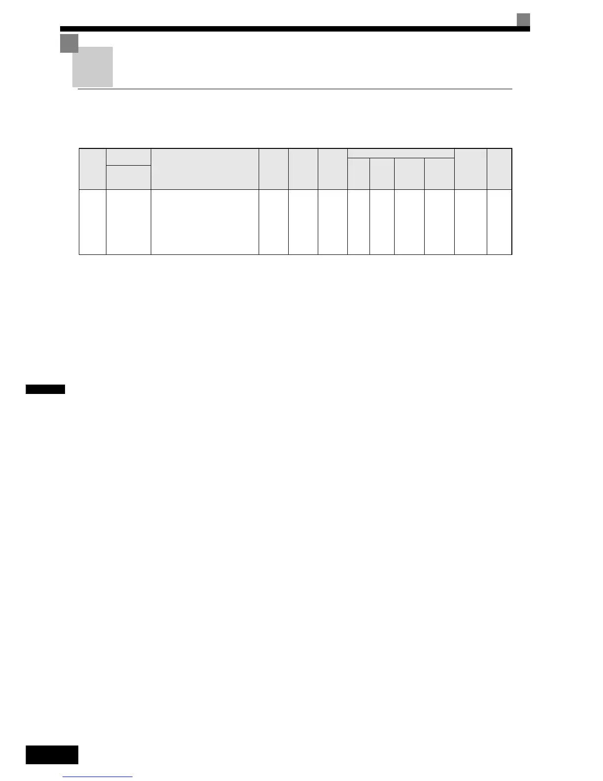
User parameter tables are structured as shown below. Here, b1-01 (Frequency Reference Selection) is used as
an example.
Param-
eter
Num-
ber
Name
Description
Setting
Range
Factory
Setting
Change
during
Opera-
tion
Control Methods
MEMO-
BUS
Register
Page
V/f
Open
Loop
Vector
Closed
Loop
Vector
Closed
Loop
Vector
(PM)
Display
b1-01
Reference
selection
Sets the frequency reference input
method.
0:Digital Operator
1:Control circuit terminal (analog
input)
2:MEMOBUS communications
3:Option Card
0 to 3 0 No Q Q Q Q 180H -
• Parameter Number: The number of the user parameter.
• Name: The name of the user parameter.
• Display The display shown in the Digital Operator JVOP-160-OY
• Description: Details on the function or settings of the user parameter.
• Setting Range: The setting range for the user parameter.
• Factory Setting:
The factory setting (each control method has its own factory setting.
Therefore the factory setting changes when the control method is
changed.)
Refer to page page 5-61, Settings which change with the Control
Mode (A1-02) for factory settings that are changed by setting the con-
trol method.
• Change during Operation:
Indicates whether the parameter can be changed or not while the
Inverter is in operation.
Yes: Changes are possible during operation.
No: Changes are not possible during operation.
• Control Methods:
Indicates the control methods in which the user parameter can be
monitored or set.
Q:
The item can be monitored and set as well in quick pro-
gramming mode as in advanced programming mode.
A:
The item can be monitored and set in advanced pro-
gramming mode only.
No:
The item cannot be monitored or set in this control
method.
• MEMOBUS Register: The register number used for MEMOBUS communications.
• Page: Reference page for more detailed information about the parameter.