9-4
9
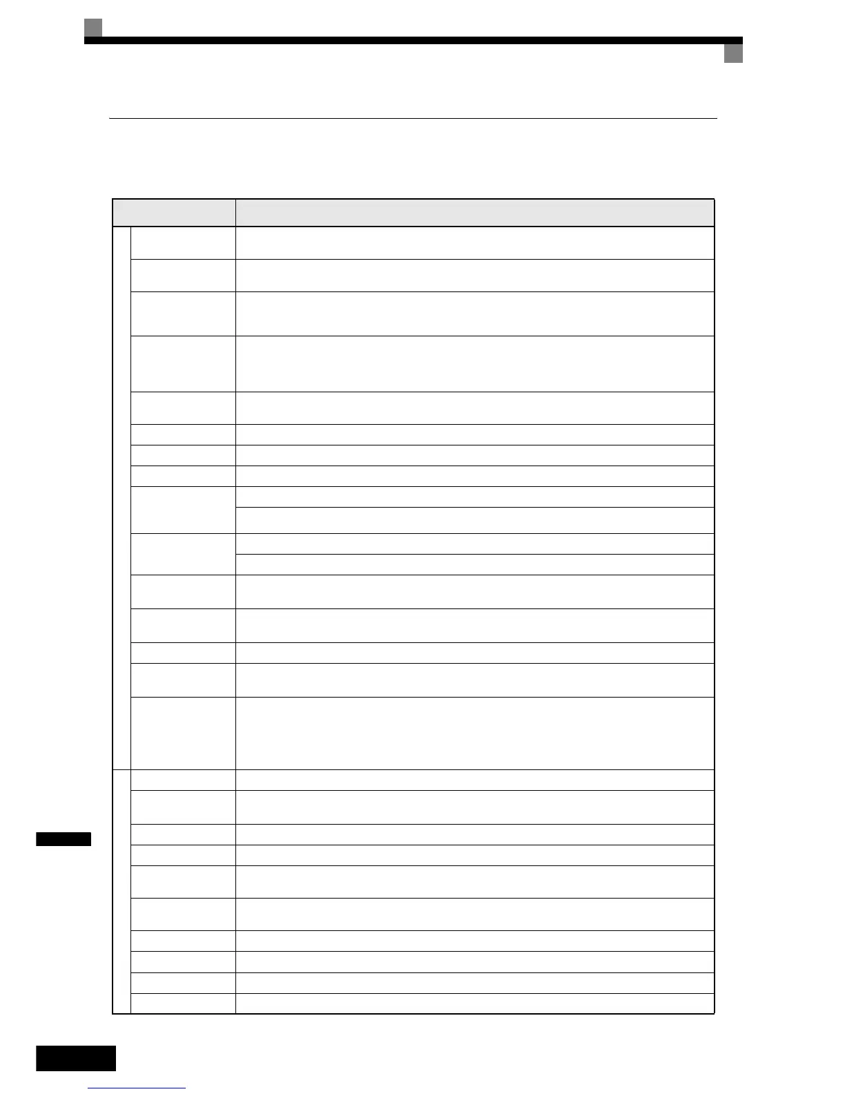
Common Specifications
The following specifications apply to both 200 V and 400 V class Inverters.
Table 9.3 Common Specifications
Model Number
CIMR-L7Z
Specification
Control Characteristics
Control method
Sine wave PWM
Closed Loop Vector control for IM and PM motors, Open Loop Vector control, V/f control
Carrier Frequency
8 kHz
higher carrier frequency possible with current derating (refer to page 9-6, Carrier Frequency Derating)
Speed control range
1:40 (V/f control)
1:100 (Open Loop Vector control)
1:1000 (Closed Loop Vector control)
Speed control accuracy
± 3% (V/f control)
± 0.2% (Open Loop Vector control)
± 0.02% (Closed Loop Vector control)
(25°C ± 10°C)
Speed control response
5 Hz (control without PG)
30 Hz (control with PG)
Torque limits Provided (4 quadrant steps can be changed by constant settings.) (Vector control)
Torque accuracy ± 5%
Frequency range 0.01 to 120 Hz
Frequency accuracy
(temperature character-
istics)
Digital references: ± 0.01% (-10°C to +40°C)
Analog references: ± 0.1% (25°C ±10°C)
Frequency setting
resolution
Digital references: 0.01 Hz
Analog references: 0.025/50 Hz (11 bits plus sign)
Output frequency reso-
lution
0.01 Hz
Overload capacity and
maximum current
150% of rated output current for 30 sec.
Frequency setting signal 0 to +10V
Acceleration/Decelera-
tion time
0.01 to 600.00 s (4 selectable combinations of independent acceleration and deceleration time settings)
Main control functions
Over torque/under torque detection, torque limits, 8-speed control (maximum), 4 acceleration and deceleration
times, S-curve acceleration/deceleration, auto-tuning (rotational or stationary), dwell function, cooling fan ON/
OFF control, slip compensation, torque compensation, auto-restart after fault, DC braking for starting and stop-
ping, automatic fault reset and parameter copy function, special Lift functions and sequences, short floor operation,
rescue operation with light load direction search, machine data copy function (save in encoder memory)
Protective Functions
Motor protection Protection by electronic thermal overload relay.
Instantaneous overcur-
rent protection
Stops at approximately 200% of rated output current.
Fuse blown protection Stops for fuse blown.
Overload protection OL2 fault at 150% of rated output current for 30 sec
Overvoltage protection
200 Class Inverter: Stops when main-circuit DC voltage is above 410 V.
400 Class Inverter: Stops when main-circuit DC voltage is above 820 V.
Undervoltage protection
200 Class Inverter: Stops when main-circuit DC voltage is below 190 V.
400 Class Inverter: Stops when main-circuit DC voltage is below 380 V.
Cooling fin overheating Protection by thermistor.
Stall prevention Stall prevention during acceleration, deceleration and running independently.
Grounding protection Protection by electronic circuits.
Charge indicator Glows when the main circuit DC voltage is approximately 10 VDC or more.