2-31
2
Wiring the Terminal Blocks
Wire Sizes (Same for All PG-Card Models)
Terminal wire sizes are shown in Table 2.15. For the ferrule types refer to Table 2.8.
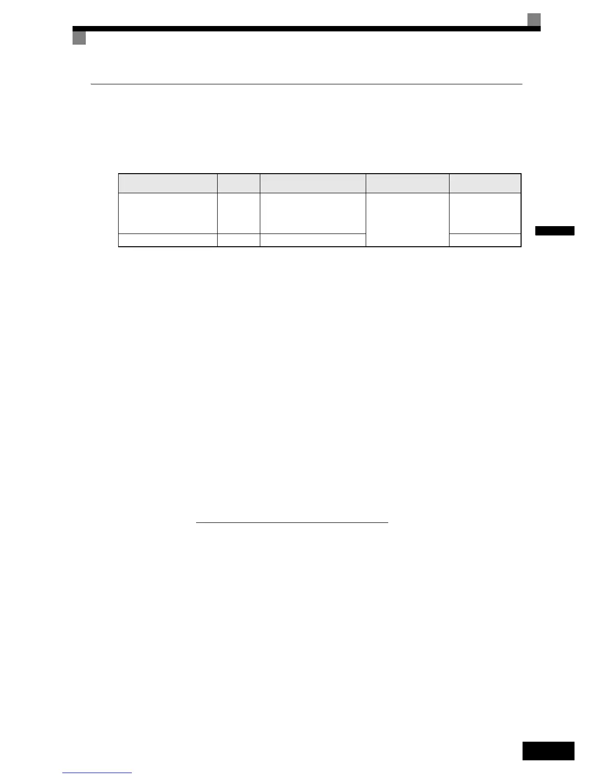
Table 2.15 Wire Sizes
Wiring Precautions
Consider the following precautions for wiring.
• Shielded twisted-pair wires must be used for signal lines. Use cables which are recommended by the
encoder manufacturer only.
• For the cable connection to the encoder connectors which are recommended by the encoder manufacturer
should be used.
• Ferrules should be used (refer to Table 2.8).
• The signal lines of the PG Speed Control Card should be separated from main power lines and other con-
trol circuits.
• The shield must be connected (green grounding cable of the option card) to the ground terminal to prevent
operational errors caused by noise.
• The wire ends should not be soldered. Doing so may cause contact faults.
• The PG cards power supply must not be used for anything other than the pulse generator (encoder). Using
it for another purpose can cause malfunctions due to noise.
• A separate power supply is required if the PG power supply consumption is higher than 200 mA. (If
momentary power loss must be handled, use a backup capacitor or other method.)
• The PG cards maximum input frequency must not be exceeded. The output frequency of the pulse genera-
tor can be calculated using the following formula.
Terminal
Terminal
Screws
Wire Thickness Wire Type Tightening Torque
Pulse generator power supply
Pulse input terminal
Pulse monitor output terminal
-
• max. 1.0 mm² for flexible wire
• max. 0.5 mm² for flexible wire
with ferrules
• max. 1.5 mm² for solid wire
Shielded, twisted-pair
wire
Shielded, polyethylene-
covered, vinyl sheath
cable
0.22 Nm
Shield connection terminal M3.5 0.5 to 2.5 mm² -
f
PG
(Hz) =
Motor speed at maximum output frequency (min
–1
)
60
x PG rating (p/rev)