2-30
2
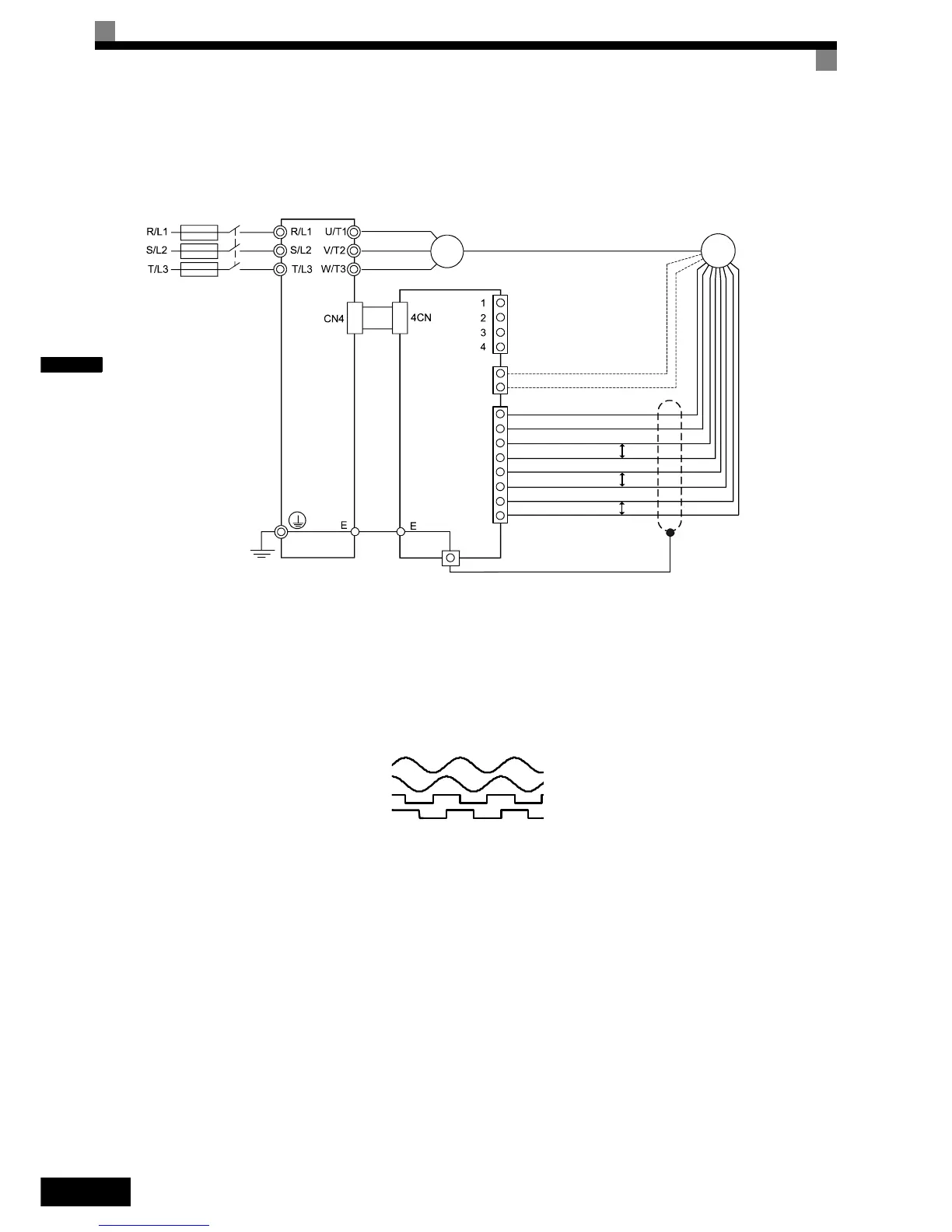
Wiring the PG-F2 Card
The following illustration shows PG-F2 option card wiring with Hiperface
y
or EnDat 2.1 encoders.
Fig 2.20 PG-F2 Wiring (EnDat signal names in brackets)
Precautions:
• The length of the pulse generator's wiring must not be more than 50m for the signal lines and 30m for
the monitor output at terminal TB3.
• The direction of rotation of the PG can be set in user parameter F1-05 (PG Rotation). The factory set-
ting is A-phase/SIN leading in forward direction (motor shaft turning counterclockwise seen from the
shaft side).
• Refer to page 2-31, Wiring Precautions for general precautions.
• The signal voltage levels must be within the following limits:
REFSIN (B-), REFCOS (A-) offset: 2.2 ~ 2.8 V
+SIN (B+), +COS (B-) peak-to-peak voltage 0.9 ~ 1.1 V
PM
PG-F2
U
S
( U
P
and U
P
sensor)
Three-phase
200 VAC
(400 VAC)
TB3
1
2
1
2
3
4
5
6
7
8
TB2
TB1
TB4
A+ Phase Output
A- Phase Output
B+ Phase Output
B- Phase Output
GND ( 0
V
UN and 0V sensor)
REFSIN ( B-)
+SIN ( B+)
REFCOS ( A-)
+COS ( A+)
Data+ ( DATA)
Data- ( /DATA)
P
P
P
( CLOCK)
( /CLOCK)
HIPERFACE® or
EnDat Encoder
SIN
COS
Pulse A
Pulse B