2-29
2
PG-F2 Option Card
Supported Encoders
The PG-F2 option card can be used in combination with the following encoder types:
• Hiperface
y
: SRS60/70
• EnDat 2.1: ECN1313, ECN113, ECN413
The maximum encoder speed shall not exceed 1200 min
-1
.
Input/Output Specifications
Table 2.14 PG-F2 I/O Specifications
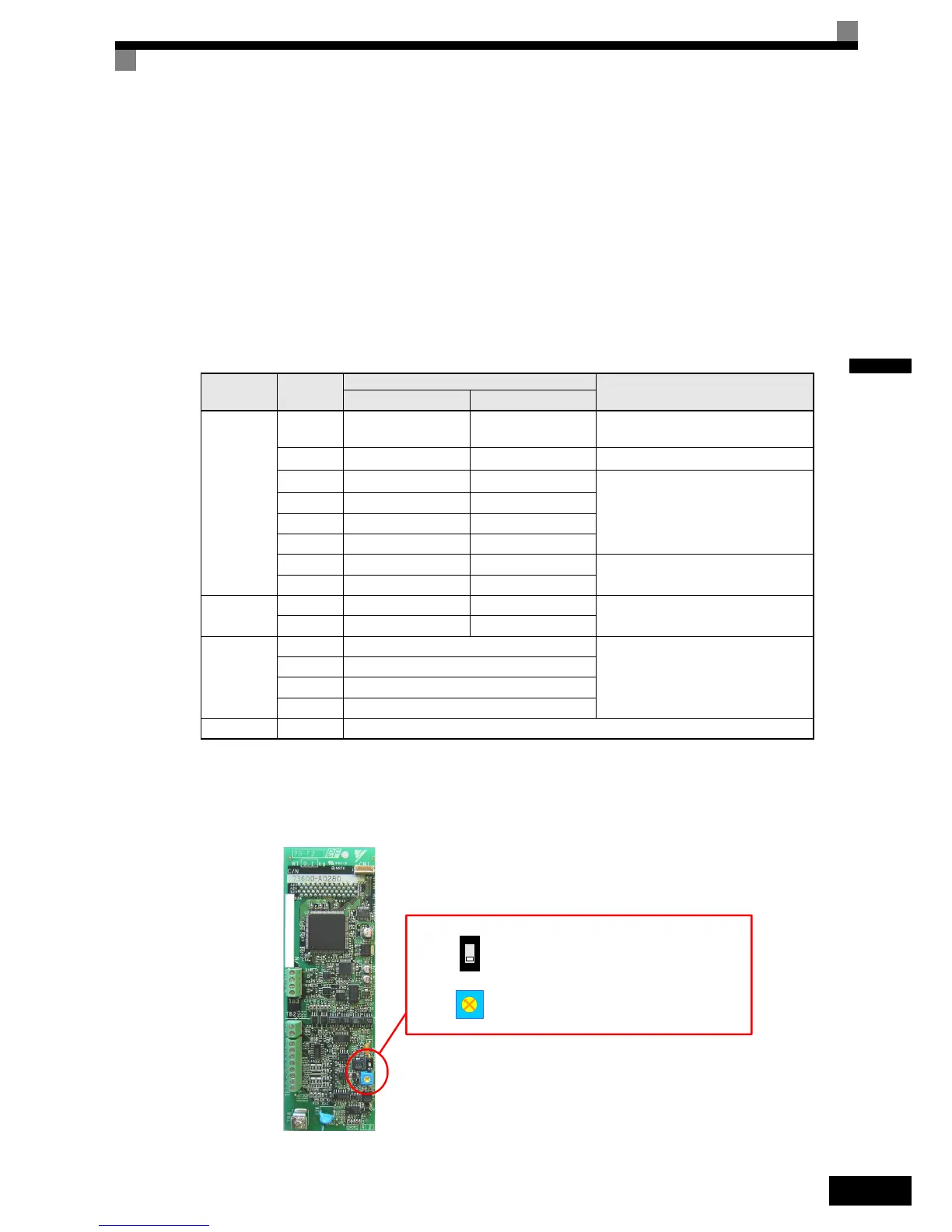
Encoder Power Supply Voltage Selection
The encoder power supply voltage must be set according to the encoder type using switch S1 on the PG-F2
card. Using potentiometer RH1 the encoder power supply voltage can be fine adjusted. The switch S1 factory
setting is OFF (EnDat is preselected). The encoder power supply is pre adjusted to 5.0~5.25V upon shipment.
Fig 2.19 PG-F2 Encoder Power Supply Voltage Selection
Terminal No.
Contents
Specifications
Hiperface
y
EnDat
TB1
1 Us 7-12V
5V U
P
and U
P
sensor
EnDat: 5VDC (±5%, max. 250 mA)
Hiperface
y
: 8VDC (±5%, max. 150mA)
2 GND
0V U
N
and 0V sensor
0V
3 REFSIN
B-
Differential inputs
4+SIN B+
5REFCOS A-
6+COS A+
7DATA+ DATA
RS-485 Data channel,
Terminating resistance: 130 Ohm
8 D ATA - / DATA
TB2
1- CLOCK
Differential output, Clock frequency: 100
kHz
2- /CLOCK
TB3
1 Pulse monitor A+
Open Collector Outputs
max 24 VDC, 30 mA
2 Pulse monitor A-
3 Pulse monitor B+
4 Pulse monitor B-
TB4 (E) Shielded sheath connection terminal
I: 8V (U
S
= 7.5 ~ 10.5 V), for HIPERFACE
OFF: 5V (U
S
= 5 V +-5%), for EnDat, (factory setting)
I
OFF
S1
RH1
S1 = I: 7.5 ~ 10.5 V, for HIPERFACE
S1 = OFF: 4.85 ~ 6.5 V, for EnDat
(factory setting: 5.0 to 5.25V)