2-28
2
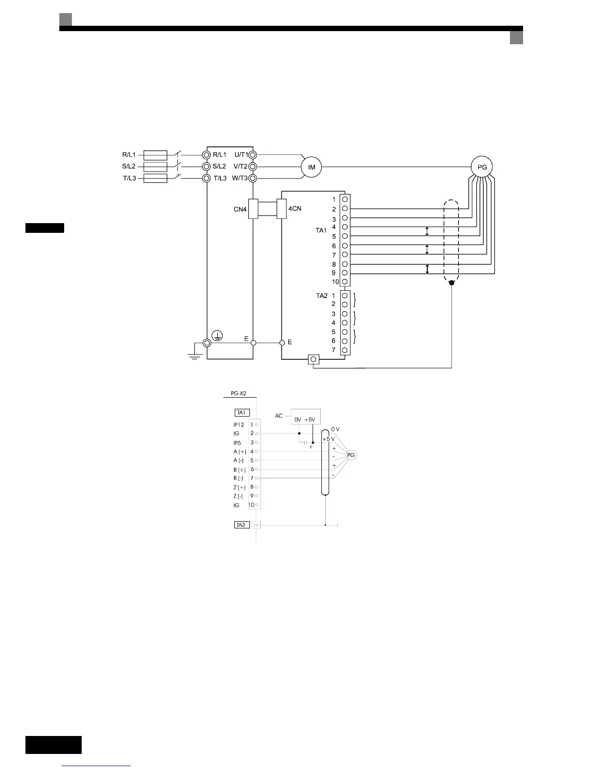
Wiring the PG-X2 card
The following illustrations show wiring examples for the PG-X2 using the option cards power supply or an
external power source for supplying the PG.
Fig 2.17 PG-X2 Wiring Using the Option Cards Power Supply
Fig 2.18 PG-X2 Wiring Using a 5 V External Power Supply
Precautions:
• The length of the pulse generator's wiring must not be more than 100 meters.
• The direction of rotation of the PG can be set in user parameter F1-05. The factory setting is A-phase
leading in forward direction (motor shaft turning counterclockwise seen from motor shaft side).
• Refer to page 2-31, Wiring Precautions for general precautions.
PG-X2
0V
+5 VDC
A+ Phase Input
A- Phase Input
B+ Phase Input
B- Phase Input
Z+ Phase Input
Z- Phase Input
A Phase Output
B Phase Output
Z Phase Output
Three-phase
200 VAC
(400 VAC)
P
P
P