2-27
2
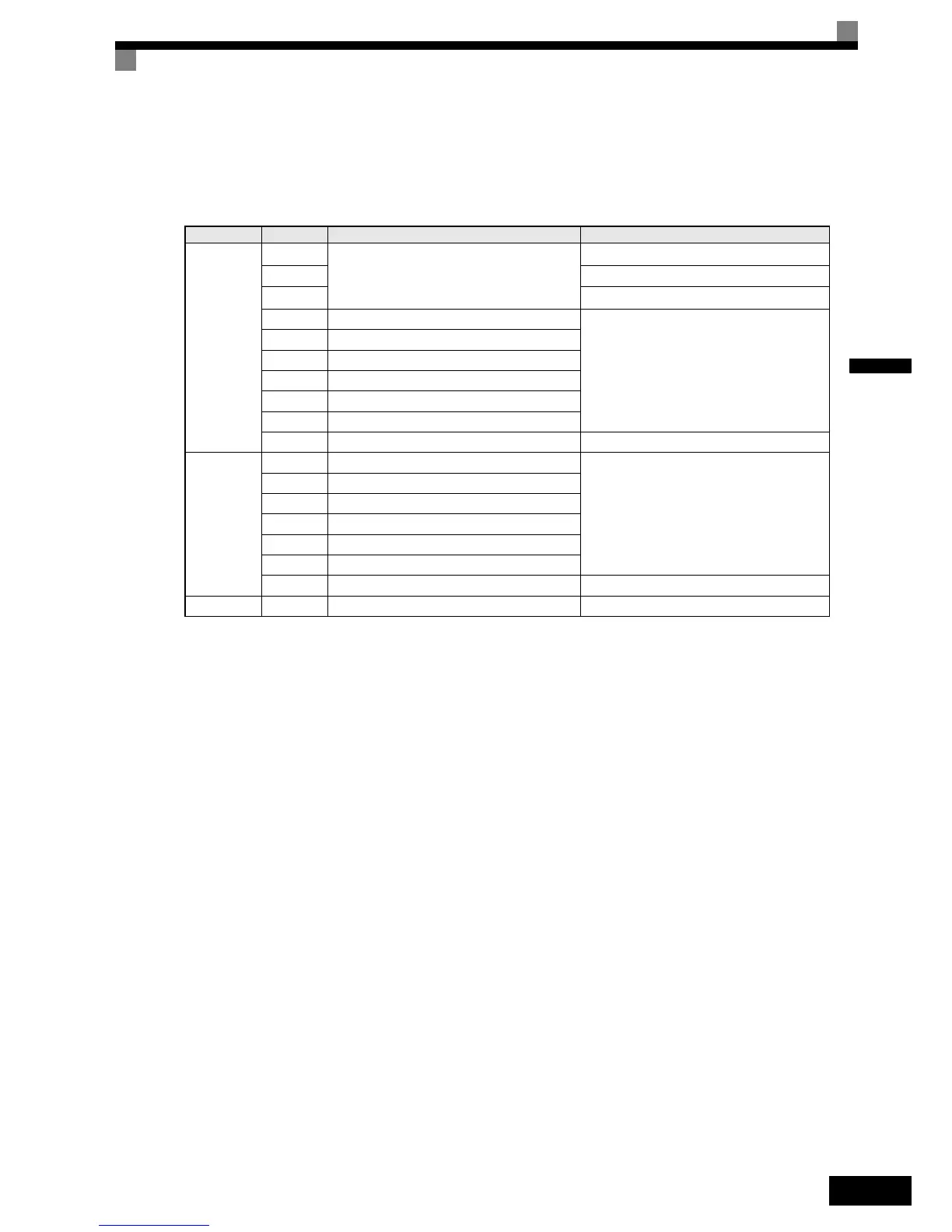
PG-X2 Option Card
Input/Output Specifications
Table 2.13 PG-X2 I/O Specifications
Ter mi na l No. Contents Specifications
TA1
1
Power supply for pulse generator
12 VDC (±5%), 200 mA max.
*1
*1. The 5V and 12V power supply should not be used at the same time.
2 0 VDC (GND for power supply)
3
5 VDC (±5%), 200 mA max.
*1
4 Pulse input terminal phase A (+)
Line driver input (RS422 level)
(maximum input frequency: 300 kHz)
5 Pulse input terminal phase A (–)
6 Pulse input terminal phase B (+)
7 Pulse input terminal phase B (–)
8 Pulse input terminal phase Z (+)
9 Pulse input terminal phase Z (–)
10 Common terminal inputs –
TA2
1 Pulse monitor output terminal phase A (+)
Line driver output (RS422 level output)
2 Pulse monitor output terminal phase A (–)
3 Pulse monitor output terminal phase B (+)
4 Pulse monitor output terminal phase B (–)
5 Pulse monitor output terminal phase Z (+)
6 Pulse monitor output terminal phase Z (–)
7 Common terminal monitor outputs –
TA3 (E) Shield connection terminal –