2-26
2
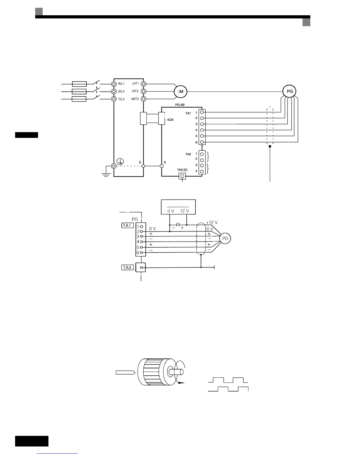
Wiring the PG-B2 card
The following illustrations show wiring examples for the PG-B2 using the option cards power supply or an
external power source for supplying the PG.
Fig 2.15 PG-B2 Wiring Using the Option Cards Power Supply
Fig 2.16 PG-B2 Wiring Using a 12 V External Power Supply
Precautions:
• The length of the pulse generator's wiring must not be more than 100 meters.
• The direction of rotation of the PG can be set in user parameter F1-05. The factory setting is A-phase
leading in forward direction (motor shaft turning counterclockwise seen from motor shaft side).
• The pulse monitor output factor can be changed using parameter F1-05.
• Refer to page 2-31, Wiring Precautions for general precautions.
Three-phase 200
VAC (400 VAC)
Inverter
Power supply +12 V
Power supply 0 V
Pulse input phase A
GND pulse input phase A
Pulse input phase B
GND pulse input phase B
Pulse monitor output phase A
Pulse monitor output phase B
CN4CN4
R/L1
S/L2
T/L3
Forward rotation of standard motor (PG)
Forward
command
Motor output axis rotates
counter-clockwise during In-
verter forward command.
Rotation
(CCW)
A-phase
B-phase
The A-phase leads (CCW) when motor rotation is forward.