6-42
6
Timing Charts
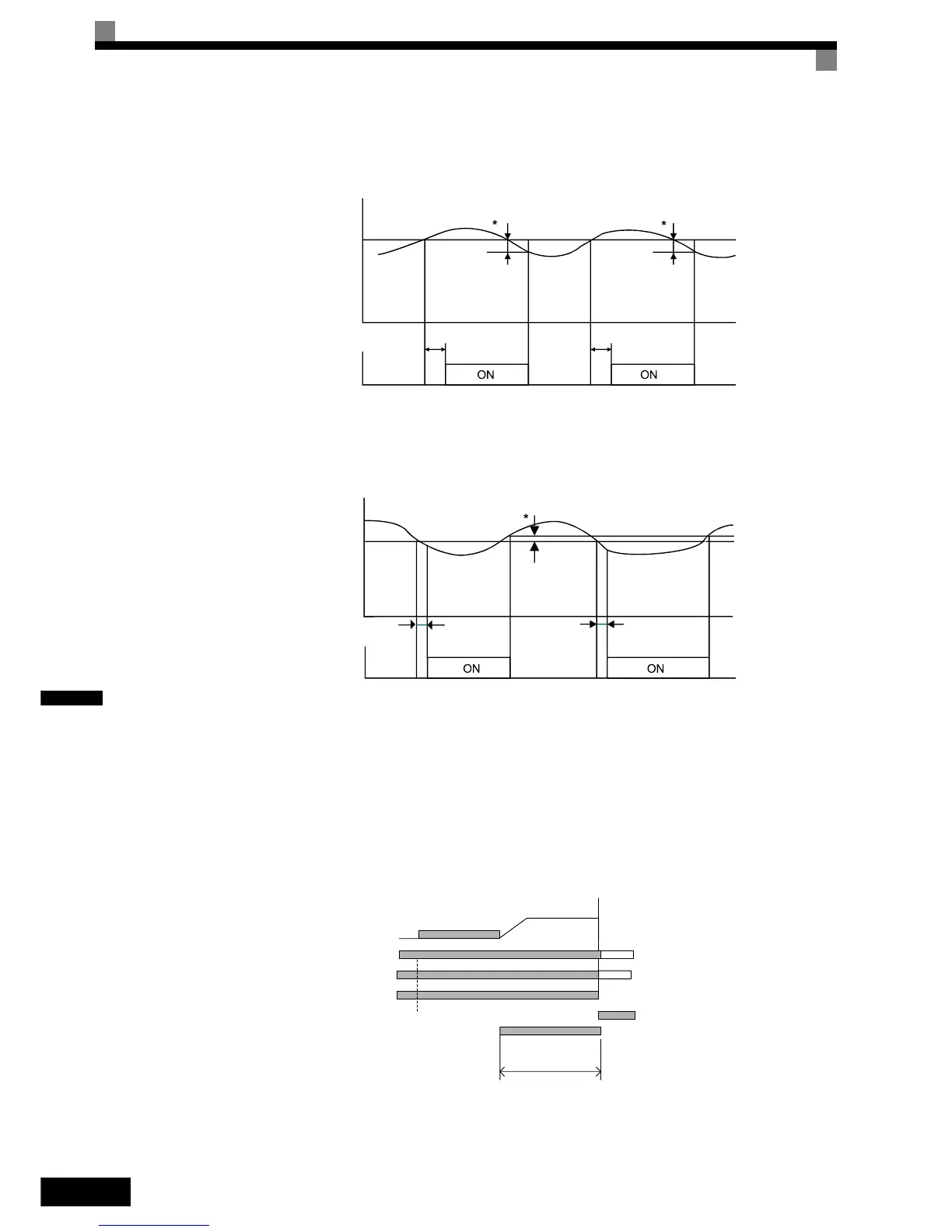
Fig 6.15 and Fig 6.16 show the timing charts for over torque and under torque detection.
Fig 6.15 Overtorque Detection
Fig 6.16 Undertorque Detection
Car Stuck Detection (OL3, Using the Overtorque detection)
The Over torque detection function can be used to detect a stuck car. The torque detection function 1 can be
used for this. Therefore a digital output has to be set to “Over torque detection 1” (H2- = B or 17). Using
this with the factory settings a car stuck is detected (output is switched) when the torque/current is higher than
150% for 10 sec. The level can be adjusted in L6-02, the time in L6-03. The output is switched of and an OL3
fault will be indicated (see Fig 6.17)
Fig 6.17 Car Stuck fault detection
Motor current (output torque)
L6-02 or L6-05
L6-03 or
L6-06
L6-03 or
L6-06
Over torque detection 1 NO
or over torque detection 2 NO
*Overtorque detection switch off bandwidth is approximately 10% of the Inverter rated output
current (or motor rated torque).
Motor current (output torque)
L6-02 or L6-05
L6-03 or
L6-06
L6-03 or
L6-06
Under torque detection 1 NO
or under torque detection 2 NO
*Undertorque detection switch off bandwidth is approximately 10% of the Inverter rated output
current (or motor rated torque).
Up/Down (D/I)
Selected Speed (D/I)
speed
DC Injection/
zero servo
Fault
Inverter enable (D/I)
detect. time
L6-03
Torque is higher
than L6-02