2-16
2
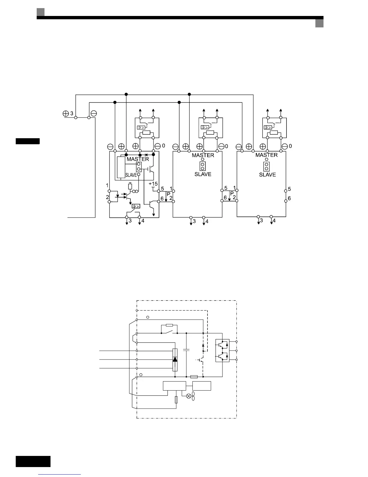
Connecting Braking Units in Parallel
When two or more Braking Units are connected in parallel the wiring and jumper settings must be done like
shown in Fig 2.8. There is a jumper for selecting whether each Braking Unit is to be a master or slave. “Mas-
ter” must be set for the first Braking Unit only, “Slave” must be set for all other Braking Units (i.e. from the
second Unit onwards).
Fig 2.8 Connecting Braking Units in Parallel
Control Power Supply Connection
The controller of the Varispeed L7 can be supplied by an external voltage source during rescue operation using
the twisted wires marked with P0 and N0. Upon shipment the wires are connected to the main circuit terminal
B1 (units up to 18.5 kW) or terminal +3 (units from 22 kW and above) and terminal -.
Fig 2.9 Control Power Supply Connection
Please refer to page 6-77, Rescue System for details about rescue operation.
Inverter
Thermal overload relay contact
Thermal overload relay contact
Thermal overload
relay contact
Braking
Resistor
Braking
Resistor
Braking
Resistor
Level
detector
Braking Unit #2
Braking Unit #3
Braking Unit #1
Thermal overload relay
contact
Thermal overload relay
contact
Thermal overload relay
contact
L1
L2
L3
R/L1
S/L2
T/L3
-
P0
N0
W/T3
V/T2
U/T1
Control
circuit
Power Supply
B1 /
B2
+ 3