PRESSURE LUBRICATION
All
engines
use
an
oil
pump
to
provide
a
constant
flow
of
oil to the engine parts. The
oil
supply collects in the oil
base where
it
is picked up by the oil pump pick-up cup.
A
by-pass valve is used
to
control oil pressure. Drain
oil
before removing oil base and always use a new gasket
when replacing the oil base.
*
*
Oil
Pump
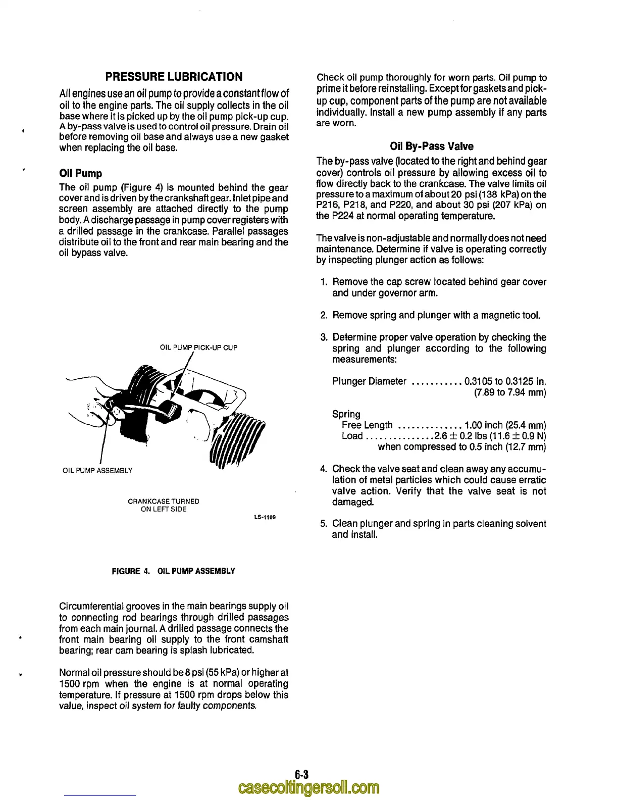
The oil pump (Figure 4) is mounted behind the gear
cover and isdriven by the crankshaft gear. Inlet pipeand
screen assembly are attached directly
to
the pump
body.
A
discharge passage in pump cover registers with
a drilled passage in the crankcase. Parallel passages
distribute oil
to
the front and rear main bearing and the
oil bypass valve.
OIL
PUMP PICK-UP CUP
~1.
OIL
PUMP
ASSEMBLY
CRANKCASE TURNED
ON
LEFT SIDE
LS-1109
FIGURE
4.
OIL
PUMP
ASSEMBLY
Circumferential grooves in the main bearings supply oil
to
connecting rod bearings through drilled passages
from each main journal.
A
drilled passage connects the
front main bearing oil supply to the front camshaft
bearing; rear cam bearing
is
splash lubricated.
A
Check oil pump thoroughly for worn parts. Oil pump to
prime
it
before reinstalling. Except for gasketsand pick-
up
cup, component parts
of
the
pump
are not
available
individually. Install a new pump assembly
if
any parts
are worn.
Oil
By-Pass
Valve
The by-pass valve (located
to
the right and behind gear
cover) controls
oil
pressure by allowing excess oil
to
flow directly back to the crankcase. The valve limits oil
pressure to a maximum
of
about 20 psi (1 38 kPa) on the
P216, P218, and P220, and about 30 psi (207 kPa) on
the P224 at normal operating temperature.
The valve is non-adjustable and normally does not need
maintenance. Determine if valve is operating correctly
by inspecting plunger action as follows:
1. Remove the cap screw located behind gear cover
and under governor arm.
2. Remove spring and plunger with a magnetic tool.
3.
Determine proper valve operation by checking the
spring and plunger according to the following
measurements:
Plunger Diameter
..........
.0.3105 to 0.3125 in.
(7.89 to 7.94 mm)
Spring
Free Length
..............
1.00
inch (25.4 mm)
Load
..............
.2.6
f
0.2 Ibs
(1
1.6
k
0.9 N)
when compressed
to
0.5
inch (12.7 mm)
4. Check the valve seat and clean away any accumu-
lation
of
metal particles which could cause erratic
valve action. Verify that the valve seat
is
not
damaged.
5.
Clean plunger and spring in parts cleaning solvent
and install.
b
Normal oil pressure should be 8 psi
(55
kPa) or higher at
1500 rpm when the engine is at normal operating
temperature.
If
pressure at
1500
rpm drops below this
value, inspect
oil
system for faulty
components.
6-3