a.
9.
Solenoid Screws
Brush Retaining Screws
Through Bolts
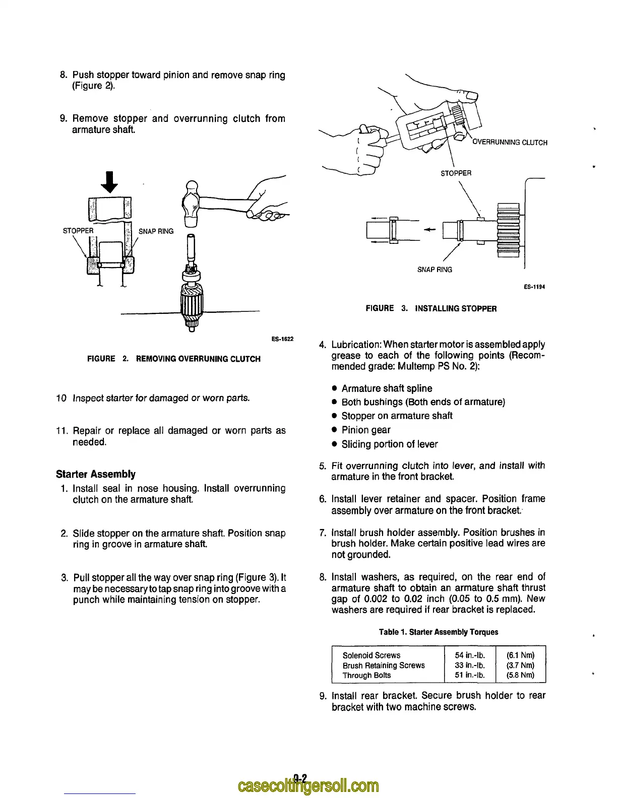
Push stopper toward pinion and remove snap ring
(Figure
2).
Remove stopper and overrunning clutch from
armature shaft.
ERRUNNING
CLUTCH
54
in.-lb.
(6.1
Nm)
33
in.-lb.
(3.7
Nm)
51
in.-lb.
(5.8
Nm)
ES-1622
FIGURE
2.
REMOVING OVERRUNING CLUTCH
10
Inspect
starter
for
damaged
or
worn
parts.
11.
Repair or replace all damaged or worn parts as
needed.
Starter
Assembly
1.
Install seal in nose housing. Install overrunning
clutch on the armature shaft.
2.
Slide stopper on the armature shaft. Position snap
ring in groove in armature shaft.
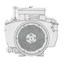
3.
Pull
stopper all the way over snap ring (Figure
3).
It
may be necessary to tapsnap ring intogroove with
a
punch while maintaining tension on stopper.
\
STOPPER
I
SNAP
AlNG
ES-1194
FIGURE
3.
INSTALLING STOPPER
4.
Lubrication: When starter motor is assembled apply
grease to each of the following points (Recom-
mended grade: Multemp
PS
No.
2):
0
Armature shaft spline
0
Both bushings (Both ends
of
armature)
0
Stopper on armature shaft
Pinion gear
0
Sliding portion
of
lever
armature in the front bracket.
5.
Fit overrunning clutch into lever, and install with
6.
Install lever retainer and spacer. Position frame
assembly over armature on the front bracket.,
7.
Install brush holder assembly. Position brushes in
brush holder. Make certain positive lead wires are
not grounded.
8.
Install washers, as required, on the rear end of
armature shaft to obtain an armature shaft thrust
gap of
0.002
to
0.02
inch
(0.05
to
0.5
mm). New
washers are required
if
rear bracket is replaced.
Table
1.
Starter Assembly Torques
9-2