THROTTLE
STOP/
SCREW
3
0
GOVERNOR
CONTROL\
I
LINKAGE
-\it
GOVERNOR
SPRING
GOVE?NOR[
\
-
ARM
-u
LOW
STOP
ADJUSTMENT
PIVOT
GOVERNOR
SIDE PULL GOVERNOR
THROTTLE
STOP
SCREW
THROTTLE
PLATE
@
GOVERNOR
CONTROL
LINKAGE
A\
GOVERNOR
"l
-1
PIVOT
GOVERNOR
-
\
SHAFT
YOKE
\
GOVERNOR
SPRING
FRONT
PULL GOVERNOR
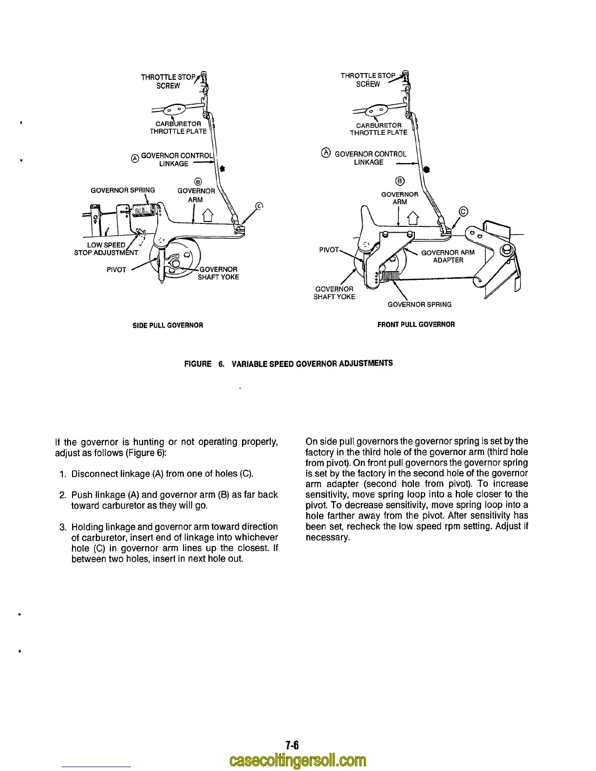
FIGURE
6.
VARIABLE SPEED
GOVERNOR
ADJUSTMENTS
If the governor is hunting or not operating properly,
adjust as follows (Figure
6):
1.
Disconnect linkage
(A)
from one of holes
(C).
2.
Push linkage
(A)
and governor arm
(B)
as far back
toward carburetor as they will go.
3.
Holding linkage and governor arm toward direction
of
carburetor, insert end
of
linkage into whichever
hole
(C)
in governor arm lines up the closest.
If
between two holes, insert in next hole out.
On side
pull
governors the governor spring is set by the
factory in the third hole of the governor arm (third hole
from pivot). On front pull governors the governor spring
is
set by the factory in the second hole
of
the governor
arm adapter (second hole from pivot).
To
increase
sensitivity, move spring loop into a hole closer
to
the
pivot.
To
decrease sensitivity, move spring loop into a
hole farther away from the pivot. After sensitivity has
been set, recheck the low speed rpm setting. Adjust if
necessary.
7-6