Tappet Adjustment
The engine is equipped with adjustable valve tappets.
The valve tappet clearance should be checked and
adjusted as specified in the Periodic Maintenance
Schedule (located in the Operator's Manual). Adjust the
valve clearance only when engine is at ambient temper-
ature. Proceed as follows:
1. Remove ignition key to prevent accidental starting.
2. Remove all parts necessary to gain access to valve
tappets.
3.
Remove spark plugs to ease the task of turning the
engine over by hand.
4. Place a socket wrench on the flywheel capscrew
and rotate the crankshaft in a clockwise direction
until the left intake valve (viewed from flywheel end)
opens and closes. Continue turning the crankshaft
until theTC markon the flywheel is lined up with the
TC mark on the gear cover. This should place the
left piston
(#I)
at the top
of
its compression stroke.
Verify that the left intake and exhaust valves are
closed and there is no pressure on the valve lifters.
5.
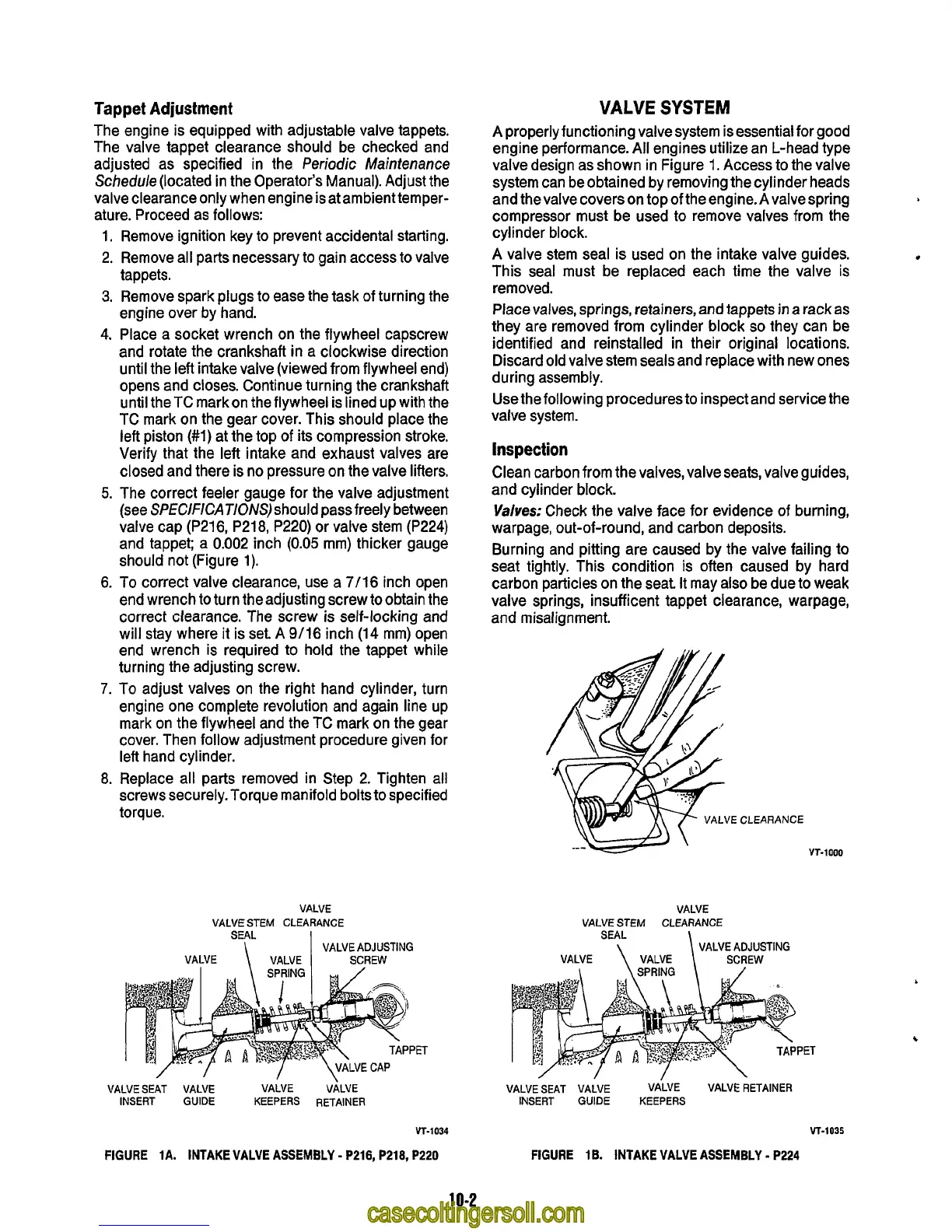
The correct feeler gauge for the valve adjustment
(see
SPE
ClFlCATI0NS)should pass freely between
valve cap (P216, P218, P220) or valve stem (P224)
and tappet; a 0.002 inch
(0.05
mm) thicker gauge
should not (Figure 1).
6. To correct valve clearance, use a 7/16 inch open
end wrench
to
turn theadjusting screw toobtain the
correct clearance. The screw is self-locking and
will stay where it is set.
A
9/16 inch (14 mm) open
end wrench is required to hold the tappet while
turning the adjusting screw.
7.
To
adjust valves on the right hand cylinder, turn
engine one complete revolution and again line up
mark on the flywheel and the TC mark on the gear
cover. Then follow adjustment procedure given for
left hand cylinder.
8.
Replace all parts removed in Step 2. Tighten all
screws securely. Torque manifold bolts to specified
torque.
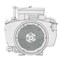
VALVE
VALVE STEM CLEARANCE
SEAL
I
VALVE ADJUSTING
VALVE
\
VALVE SCREW
VALVE
SYSTEM
A
properly functioning valvesystem is essential for good
engine performance.
All
engines utilize an L-head type
valve design as shown in Figure
1.
Access to the valve
system can be obtained by removing the cylinder heads
and thevalve coverson
topoftheengine.Avalvespring
compressor must be used to remove valves from the
cy1 inder block.
A valve stem seal is used on the intake valve guides.
This seal must be replaced each time the valve is
removed.
Place valves, springs, retainers, and tappets
in
a rack
as
they are removed from cylinder block
so
they can be
identified and reinstalled in their original locations.
Discard old valve stem seals and replace with new ones
during assembly.
Use the following procedures to inspect and service the
valve system.
Inspection
Clean carbon from thevalves, valve seats, valve guides,
and cylinder block.
Valves:
Check the valve face for evidence of burning,
warpage, out-of-round, and carbon deposits.
Burning and pitting are caused by the valve failing to
seat tightly. This condition
is
often caused by hard
carbon particles on the seat It may also be due to weak
valve springs, insufficent tappet clearance, warpage,
and misalignment.
VALVE
VALVE STEM CLEARANCE
SEAL
\
\
VALVE
ADJUSTING
PET
VALVE SEAT VALVE
VALVE
VALVE
INSERT GUIDE KEEPERS RETAINER
VALVE SEAT VALVE VALVE
VALVE
RETAINER
INSERT GUIDE KEEPERS
c
VT-1034
FIGURE 1A. INTAKE VALVE ASSEMBLY
-
P216, P218, P220
WIT-1035
FIGURE 1B. INTAKE VALVE ASSEMBLY
-
P224
10-2