10
REMOTE
CONTROL
RLRL
ININ
IN
IN
IN
COAXIAL
OPTICAL
IN
IN
IN
IN
FRONT
SURR
CENTER
SUB
WOOFER
VIDEO 2
VIDEO 1
OUT
IN
IN
OUT
OUT
OUT
DIGITAL INPUT
VIDEO 2VIDEO 3
VIDEO 1
DVD MONITOR
OUT
VIDEO
S VIDEO
DVD
TAPE
CD
FRONT
SPEAKERS A
FRONT
SPEAKERS B
L
R
IN
VIDEO 3
RL
SURROUND
SPEAKERS
CENTER
SPEAKER
L
R
AC OUTLET
ANTENNA
FM
75
AM
SUBWOOFER
PRE OUT
RL RL
AUDIO OUT
(PLAY)
AUDIO IN
(REC)
RL
AUDIO OUT
(PLAY)
DIGITAL
OUT
OPTICAL
S VIDEO
IN
VIDEO
IN
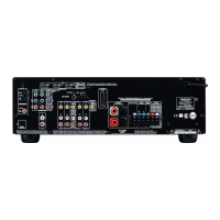
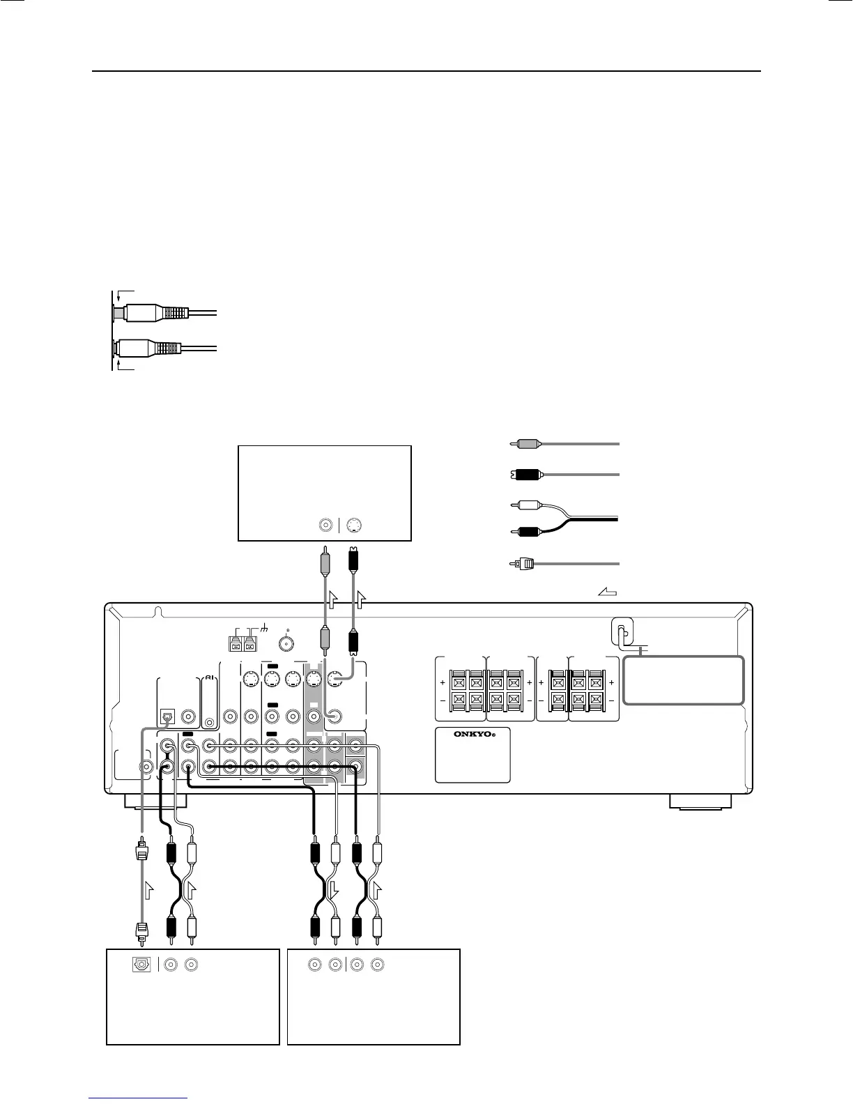
Connecting to audio/video equipment
Audio connection cable
(Analog signal)
Optical fiber cable
(Digital signal)
Optical plug
Signal flow
Audio (R)
Cassette Tape deck, MD recorder,
DAT deck, CD recorder (TAPE)
CD player (CD)
TV monitor or Projector
(MONITOR OUT)
S video connection cable
(S video signal)
S video plug
Video connection cable
(Analog signal)
VIDEO
Refer to “Cautions
regarding Video Signal”
above.
Before connecting
• Be sure to always refer to the instruction manual that came
with the component that you are connecting.
• Do not plug in the power cord until all connections have
been made.
• For input jacks, red connectors (marked R) are used for the
right channel, white connectors (marked L) are used for the
left channel, and yellow connectors (marked VIDEO) are
used for video connection.
• Insert all plugs and connectors securely. Improper connections
can result in noise, poor performance, or damage to the
equipment.
• Do not bind audio connection cables with power cords and
speaker cables. Doing so may adversely effect the sound
quality.
Improper connection
Inserted completely
• To connect the digital output from a component
connected to the TAPE jacks to this unit, use the
OPTICAL or COAXIAL input jack.
In this case, it is required to change the assignment of
digital inputs to input sources by referring to “Setting the
digital inputs” on page 21.
• The TAPE OUT jack does not output the signal input
from the DIGITAL INPUT jack. (The digital signal is not
converted into an analog signal.)
• To connect the digital output from CD player connected
to the CD jacks to this unit, use the OPTICAL input jack.
To connect the digital output to the COAXIAL input jack
of this unit, it is required to change the assignment of
digital inputs to input sources by referring to “Setting the
digital inputs” on page 21.
DO NOT connect the
power cord at this
time.
Cautions regarding Video Signal
This product has both S VIDEO and VIDEO terminals for video
signals (the VIDEO 3 input has only a VIDEO terminal) .
S VIDEO provides better picture quality than VIDEO. You can
make connections to either of these terminals. This unit outputs
signals input to the S VIDEO IN terminals only. Likewise signals
input to the VIDEO IN terminals are only output from the VIDEO
OUT terminals. Therefore, connect your TV to S VIDEO if your
DVD player or VCR is connected to S VIDEO. If they are
connected to VIDEO, connect your TV to VIDEO.
It is necessary to connect your TV to both S VIDEO and VIDEO if
you have some equipment that is connected only to S VIDEO and
some equipment that is connected to only VIDEO. In such a case,
both S VIDEO and VIDEO connections are also necessary to
record to VIDEO 1.
Audio (L)
 Loading...