RG2 User Manual – Version 1.44
Specifications is periodically reviewed and may change without notice Copyright © 2015 – 2016 by On Robot ApS. All rights reserved
5 Electrical interface
This chapter describes all the electrical interfaces of the gripper. The term “I/O” refers to both digital and analog
control signals going from or to the gripper.
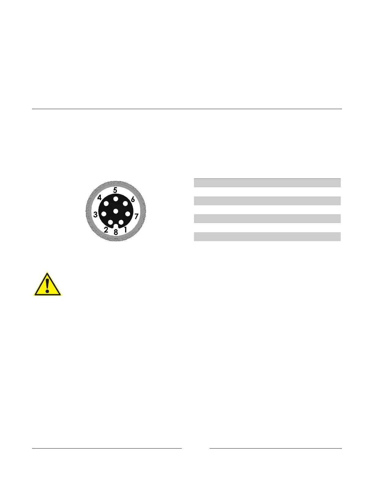
5.1 Tool connections
The Gripper cable is intended to fit the tool connector on robots from Universal Robots. The connections are
described below. The output tool connector on the gripper shares the same connections as the input cable
described below.
CAUTION:
1. If the gripper is used in applications were it is not connected to a UR robot.
i. Make sure the connections resembles the analog input, digital in and outputs
and the power connections.
ii. Make sure you use a RG2 gripper programming
script that are adapted to fit your specific application.
For more information, please contact your supplier.
2. Do not operate the gripper in a wet environment.
5.1.1 Power supply
The gripper can operate at both 12V and 24V. Please Note that at 12V the forces, speed and some of the function
tolerances described in this manual does not apply. It is recommended to use 24V.