range Pi 用户手册 深圳市迅龙软件有限公司版权所有
www.orangepi.cn
19
www.xunlong.tv
2.6. Start the Orange Pi development board
1) Insert the TF card with flahsed image into the card slot of the board
2) The development board has an Ethernet port, which can be plugged into a network
cable for Internet access
3) Connect a 5V/2A (5V/3A is also available) high-quality power adapter
a. Remember not to plug in the 12V power adapter, if you plug in the 12V
power adapter, it will burn the development board
b. Many unstable phenomena during system power-on and startup are
basically caused by power supply problems, so a reliable power adapter is
very important
2) If you want to view the output information of the system through the debug serial port,
please use the USB to TTL module and DuPont cable to connect the development board
to the computer. For the connection method of the serial port, please refer to the section
on the use of the debug serial port
3) Then turn on the switch of the power adapter, if everything is normal, the serial
terminal can see the output log of the system startup at this time
2.7. How to use the debug serial port?
2.7.1.
Debug serial port connection instructions
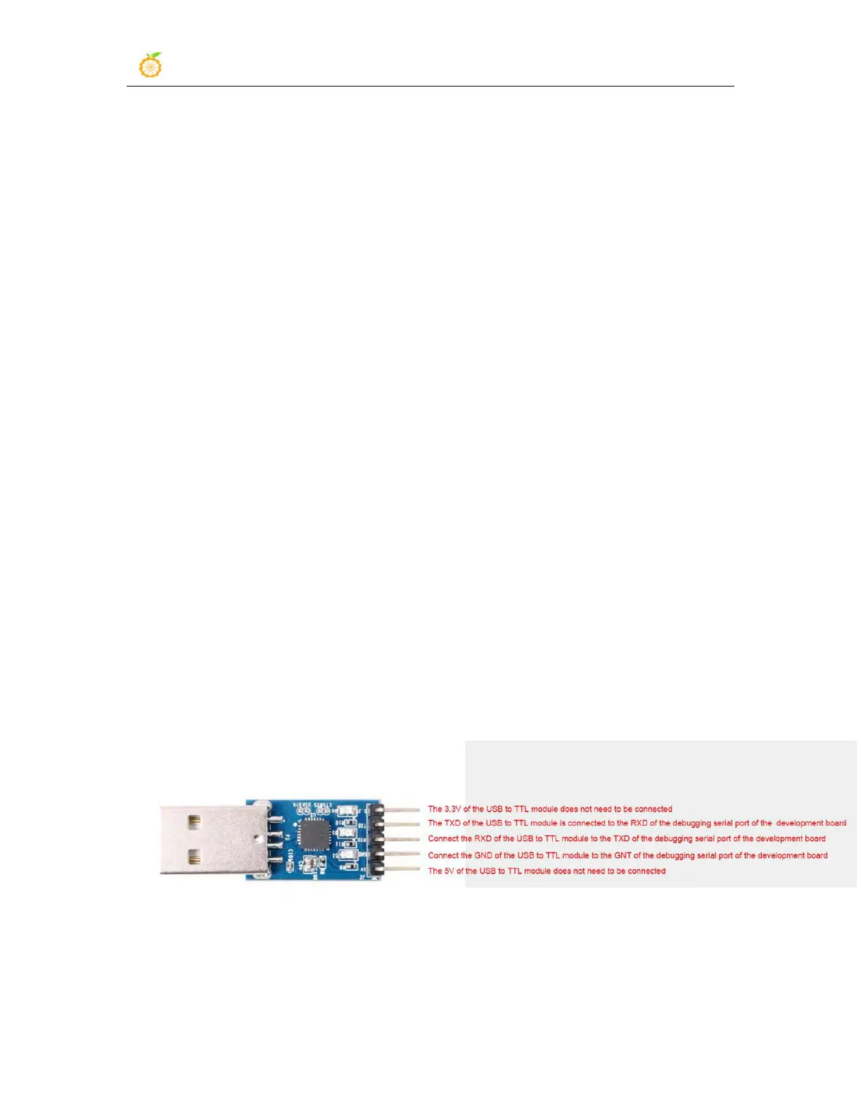
1) First, you need to prepare a USB to TTL module. This module can be bought in
Orange Pi Store. If there are other similar USB to TTL modules, you can also insert the
USB port of the USB to TTL module into the USB of the computer Interface
2) The corresponding relationship between the debug serial port GND, TX and RX pins
of the development board is shown in the figure below