range Pi 用户手册 深圳市迅龙软件有限公司版权所有
www.orangepi.cn
73
www.xunlong.tv
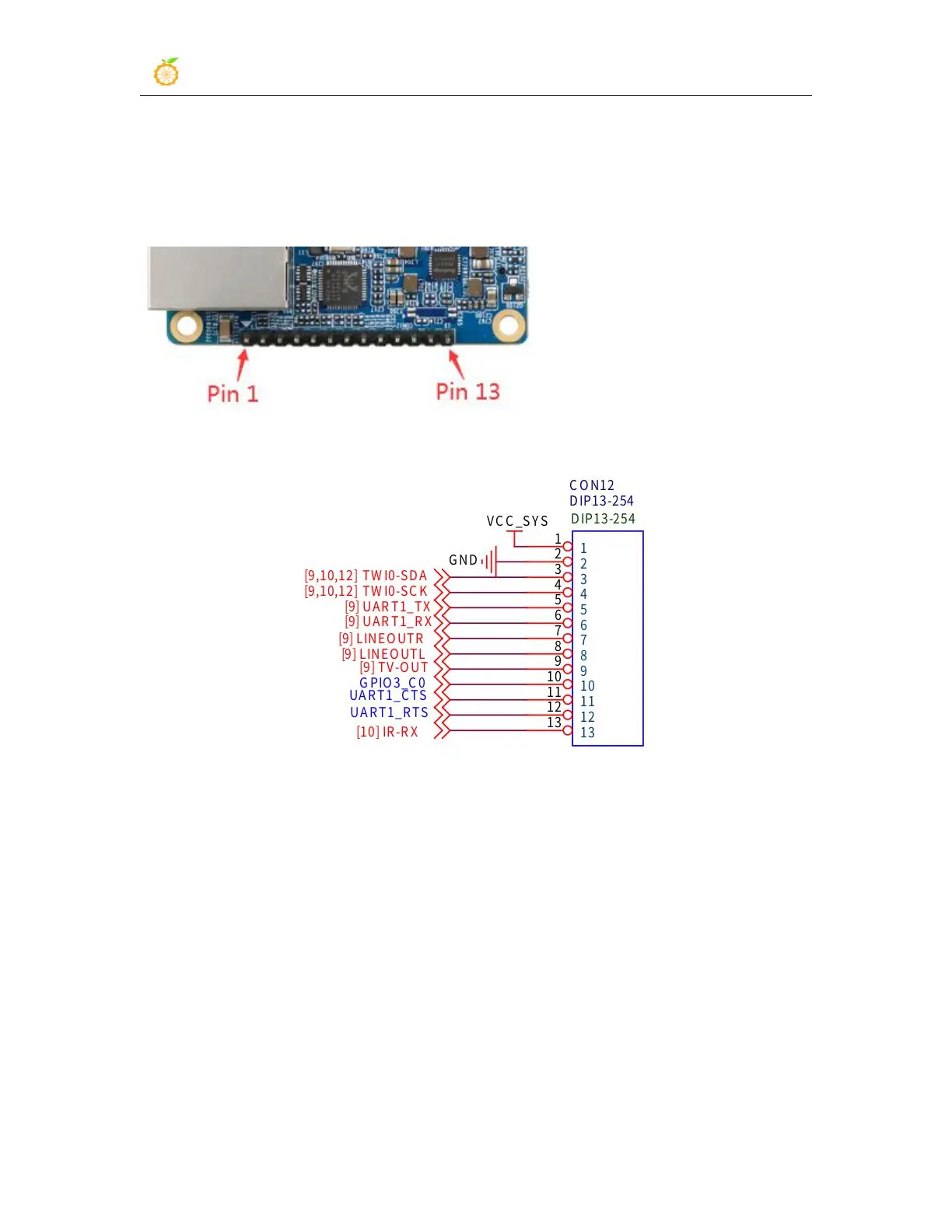
5.16. 13Pin transfer board interface pin description
1) Please refer to the figure below for the sequence of the 13 pin interface of the Orange
Pi R1 Plus development board
2) The schematic diagram of the 13pin interface of the Orange Pi R1 Plus development
board is shown below
3) The function description of the 13 pin adapter board interface pins of Orange Pi R1
Plus development board is as follows
a. When the 13pin pin is connected to the adapter board, it can be additionally
provided
a) TV-OUT audio and video output
b) Infrared receiving function
c) The 3rd, 4th, 5th, 6th, 10th, 11th and 12th pins of the 13pin interface cannot
be used after the adapter board is connected
d) Also note that the MIC and 2*USB on the 13pin adapter board cannot be
used on Orange Pi R1 Plus
b. When the 13 pin interface of the Orange Pi R1 Plus development board is not
connected to the adapter board, pins 3, 4, 5, 6, 10, 11, 12 and 13 can be used as ordinary