ExpressBox 16 Basic| 35
NOTE
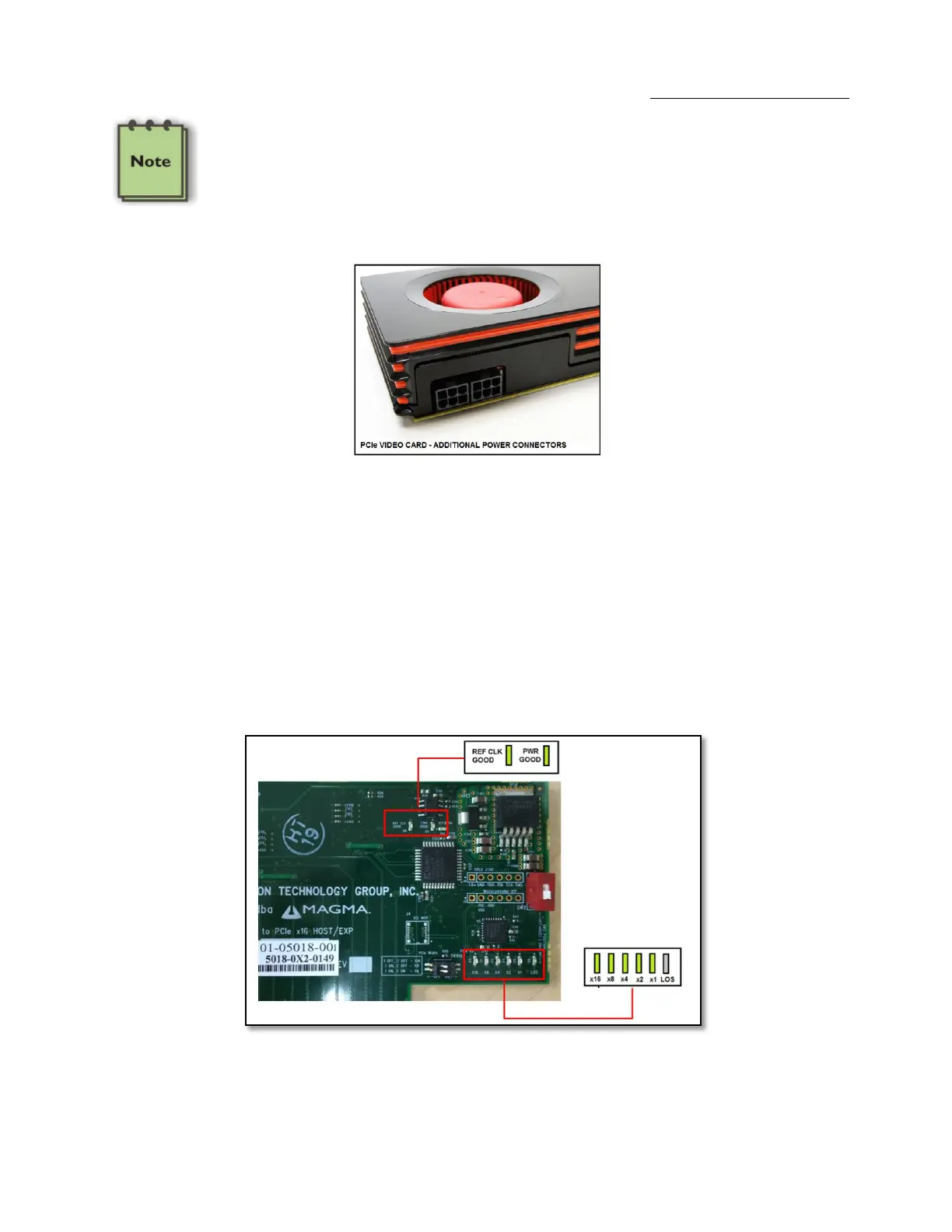
CONNECTORS J20, J21, J22, and J23 within the chassis will provide additional power to any PCI Express Card that requires
it. The outputs from these connectors are 12V @ 10A each. Users should purchase a OSS cable P/N# 01-05996-03 for this
capability. The connector on the 3
rd
Party PCI Express card that is compatible with the cable is shown below. The AUX
power adapter typically comes with the PCIe card.
Before discussing a troubleshooting methodology for locating the problem we will first introduce several indicators and configuration switches
that provide general and specific information for this process.
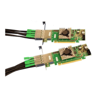
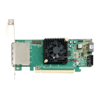
4.3 Interface Cards
4.3.1 x16 Interface Card LEDs
The host card has indicators that provide the status of the clock, the power distribution, and the active data lanes. To verify that your expansion
device is properly linked to your computer, ensure that these LEDS on the HIF and EIF cards are ON:
If the card is not transferring or receiving any type of data through its transceiver (iPass connector) then the LOS (Loss of Signal) LED would be
turn ON.