OTTO 1 00 Fast Charger • OMM- 000037 • REV. H
38
© Clearpath Robotics Inc. 2020. All rights reserved. CLEARPATH and OTTO are trademarks of Clearpath Robotics Inc. All other product and company names listed are trademarks
or trade names of their respective companies. The information contained in these documents is the Confidential and/or Proprietary property of Clearpath Robotics Inc. and may not
be duplicated, reproduced or further disclosed without the express written approval of Clearpath Robotics Inc.
10.2.4 Power Wire Installation
1. Confirm the cable that contains the power and signal lines spans comfortably between the Charger
Electronic Unit and Charge Dock.
2. Pass the power lines and signal lines from the Charger Electronic Unit through the right-side Charge
Dock tower cover cord grip.
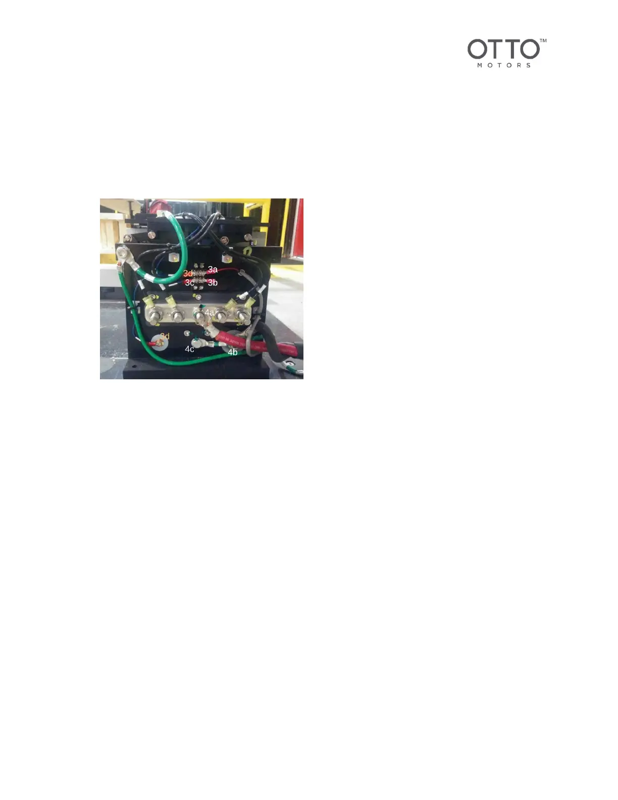
Figure 14 Right Charge Tower Power and Signal Lines
3. Attach the signal lines to the right-side Charge Dock Tower (see above).
a. Red signal from Charger Electronic Unit to top-right small terminal. Torque to 5.2 Nm.
b. Black signal from Charger Electronic Unit to bottom-right small terminal. Torque to 5.2 Nm.
c. Signal contact to bottom-left small terminal block. Torque to 5.2 Nm.
d. Jumper cable from top-left small terminal block to smaller diameter copper slug. Torque to
5.2 Nm.
4. Attach the power lines to the right-side Charge Dock Tower (see above).
a. Red power ring terminal to center of the five-position terminal block. Torque to 24.5
Nm. Replace terminal block cover.
b. Black ground cable ring terminal to copper slug on outside edge of wall charge tower.
Torque to 6.2 Nm.
c. Green bonding wire ring terminal to grounding stud near bottom-center. Torque to 6.2 Nm.
Ensure the external tooth washer is between the ring terminal and the tower and penetrates
the surface finish for a good electrical connection
5. Install the right-side Charge Dock tower cover.
6. Push on the cover until it pops into position. Install retaining screw with external tooth washer.
Torque to 12.5 Nm.