26
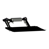
Installing lifting mechanism
7.1.4 Positioning the stand tube
Adjust the stand tube height according to the general assembly
diagram. Ensure the greatest possible ground clearance and the
free movement of all components.
Move the stand tube into the horizontal position so that the top
edge is parallel to the vehicle body.
Secure the stand tube with screw clamps.
7.1.5 Fixing the lifting mechanism to console plates on the
vehicle chassis
Attachment of the lifting mechanism to the vehicle chassis depends
on the type of console plates used. The following console pates can
be ordered from PALFINGER Tail Lifts:
• welded consoles
• bolted consoles
The installation sequence differs according to the type of console
plates used.
The welded consoles are attached in advance by PALFINGER Tail
Lifts to the lifting mechanism. The customer notifies PALFINGER
Tail Lifts of the required distances between the consoles and these
cannot be subsequently changed. The lifting mechanism is attached
with the console plates to the vehicle chassis.
The bolted consoles are first adjusted on the lifting mechanism to
the chassis size and then fixed. Together with the lifting mechanism,
they are then attached to the vehicle chassis. The long holes in the
bolted consoles make transverse adjustments possible.
 Loading...