Getting started
VQT3C84
11
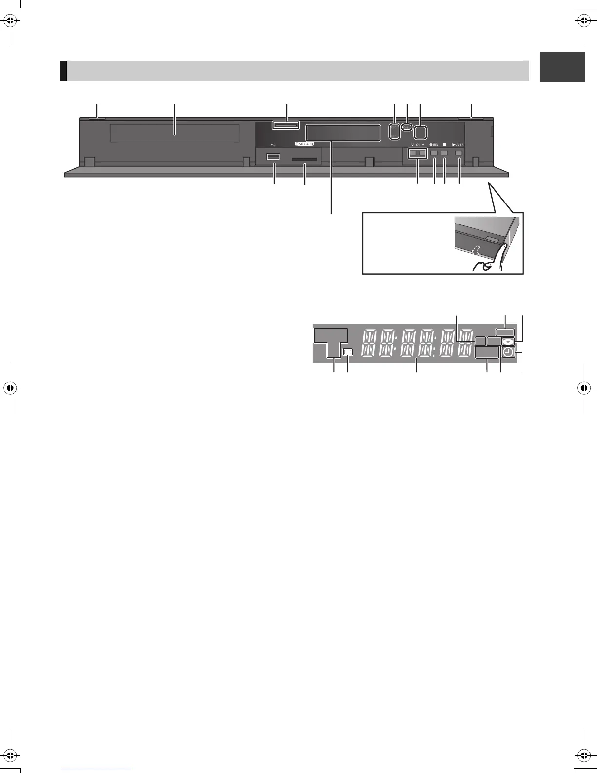
1 Standby/on switch (Í/I) (> 18, 20)
Press to switch the unit from on to standby mode or vice
versa. In standby mode, the unit is still consuming a
small amount of power.
2 Disc tray (> 18)
3 Blue LED
≥It is possible to set the LED to turn on/off. (> 80)
4 Recording indicator
≥The indicater will light up while recording.
≥The indicator will blink while recording is paused.
5 CALL LED
≥The LED will light up when this unit receives incoming
call etc. of the video communication. (> 67)
6 Remote control signal sensor
– Angle: Approx. 20° up and down, 30° left and right
– Distance: Within approx. 7 m in front of the unit
7 Open/close disc tray (> 18)
8 USB port (> 18)
9 SD card slot (> 18)
: Channel select (> 24)
; Start recording (> 28)
< Stop
= Start play
> Display
1 SD card slot indicator
2 Copying indicator (> 47)
3Disc indicator
4 Drive (HDD, BD or SD) indicator
5 Remote control signal indicator
6 Main display section indicator
Current time/playback counter, various messages
7 Playback indicator
8 USB port indicator
9 Timer recording indicator
This indicator lights up when the timer recording
standby is activated.
¾ Rear panel terminals (> 12–17)
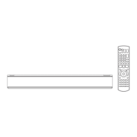
Main unit
Pull to flip down the
front panel.
PLAY
COPY
SD USB
HDDSD
BD
123
45
6789
DMRPWT500GL_eng.book 11 ページ 2011年2月17日 木曜日 午後1時17分
 Loading...