7.5 PWM Output Function
7.5.1 Overview
PWM output function
With the F173 (PWMH) instruction, the pulse width modulation output of the specified duty ratio is
obtained.
7.5.2 Instruction to be Used for PWM Output Function
PWM Output Instruction F173
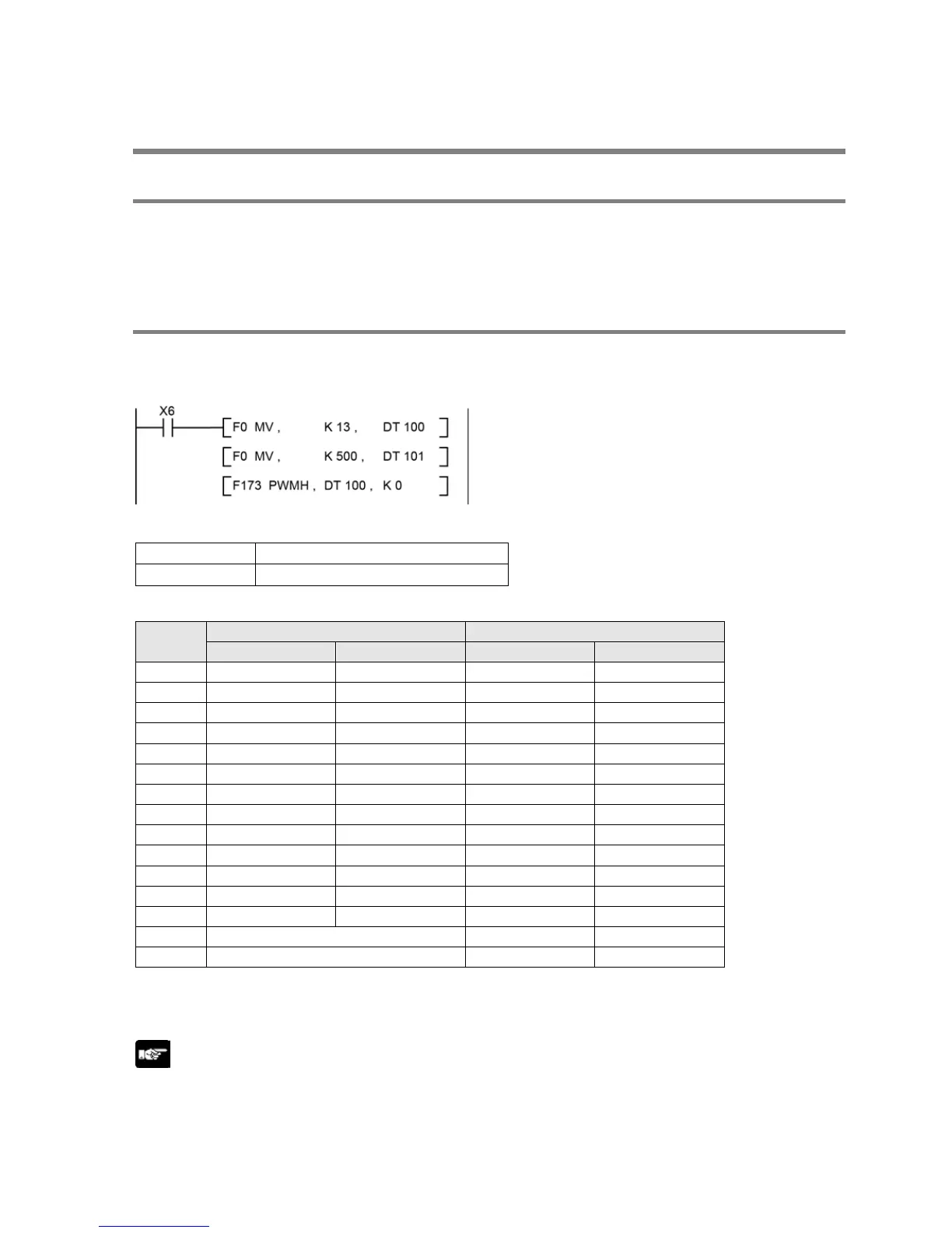
In the program below, while X6 is on, a pulse with a period of 1 ms and duty ratio of 50% is output from
Y0 of specified channel CH0.
K3 6 166.67 6 166.67
K4 7.5 133.33 7.5 133.33
K5 12.5 80.00 12.5 80.00
K6 25 40.00 25 40.00
K7 50 20.00 50 20.00
K8 100 10.00 100 10.00
K9 200 5.00 200 5.00
K10 400 2.50 400 2.50
K11 600 1.67 600 1.67
K12 800 1.25 800 1.25
K13 1.0 k 1.00 1.0 k 1.00
K14 1.2 k 0.833 1.2 k 0.833
K15 1.6 k 0.625 1.6 k 0.625
K16 Cannot specify (Operation error) 2.0 k 0.50
K17 Cannot specify (Operation error) 3.0 k 0.333
*2: Specify the duty by setting the K constant.
Duty: K0 to K1000 (1000 resolutions)
Note:
- When a value out of the settable range is written in the control code, an operation error will occur.
- If a value out of the settable range is written to the duty area while the instruction is being executed, a
frequency corrected to the maximum value will be output.
 Loading...


