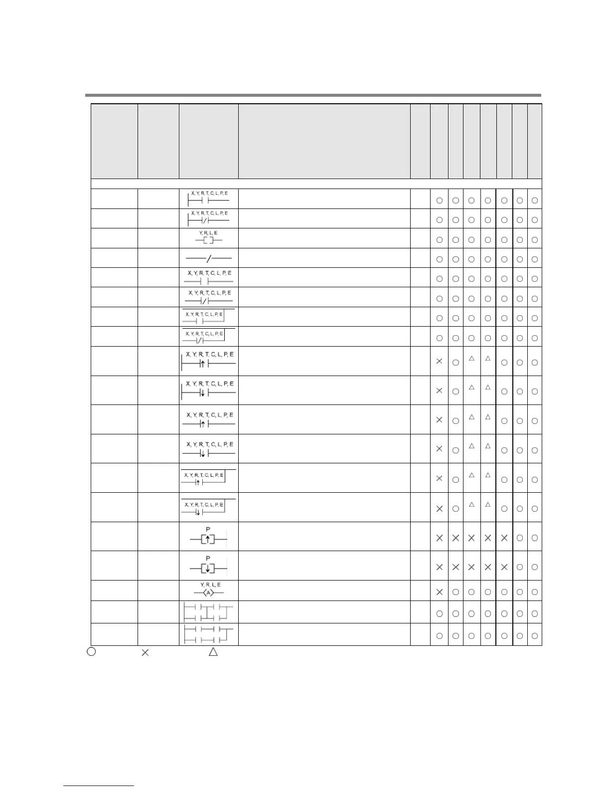
14.2 Table of Basic Instructions
Name Boolean Symbol Description
Steps *3
FP0/FP-e
FP0R
FP
FP-X
FP-X0
FP2
FP2SH/FP10SH
Sequence basic instructions
Begins a logic operation with a Form A
(normally open) contact.
1
(2)
Begins a logic operation with a Form B
(normally closed) contact.
1
(2)
Outputs the operated result to the specified
output.
1
(2)
Not /
Inverts the operated result up to this
instruction.
1
AND AN
Connects a Form A (normally open) contact
Connects a Form B (normally closed) contact
Connects a Form A (normally open) contact in
parallel.
Connects a Form B (normally closed) contact
in parallel.
Begins a logic operation only for one scan
when the leading edge of the trigger is
Begins a logic operation only for one scan
when the trailing edge of the trigger is
Connects a Form A (normally open) contact
serially only for one scan when the leading
edge of the trigger is detected.
2
*2
*2
Trailing
edge AND
AN
Connects a Form A (normally open) contact
serially only for one scan when the trailing
edge of the trigger is detected.
2
*2
*2
Leading
edge OR
OR
Connects a Form A (normally open) contact in
parallel only for one scan when the leading
edge of the trigger is detected.
2
*2
*2
Trailing
edge OR
OR
Connects a Form A (normally open) contact in
parallel only for one scan when the trailing
edge of the trigger is detected.
2
*2
*2
Outputs the operated result to the specified
output only for one scan when leading edge of
the trigger is detected. (for pulse relay)
Outputs the operated result to the specified
output only for one scan when trailing edge of
the trigger is detected. (for pulse relay)
Inverts the output condition (on/off) each time
the leading edge of the trigger is detected.
3
Connects the multiple instruction blocks
Connects the multiple instruction blocks in
parallel.
1
: Available, : Not available, : Not available partially
*1) The type of the devices that can be specified depends on the models.
*2) This instruction is available for FP-X Ver. 2.0 or later, and FPΣ Ver. 3.10 or later.
*3) In the FP2/FP2SH/FP10SH, when X1280, Y1120, R1120 (including special internal relay), L1280, T256 or C256 is
specified by ST, ST/, OT, AN, AN/, OR or OR/ instruction, the number of steps is shown in parentheses. Also, in the
FP2/FP2SH/FP10SH, when a relay number has an index modifier, the number of steps is shown in parentheses. For the
FPΣ, FP-X and FP-X0, the number of steps varies according to the relay number to be used.
Phone: 800.894.0412 - Fax: 888.723.4773 - Web: www.clrwtr.com - Email: info@clrwtr.com
 Loading...


