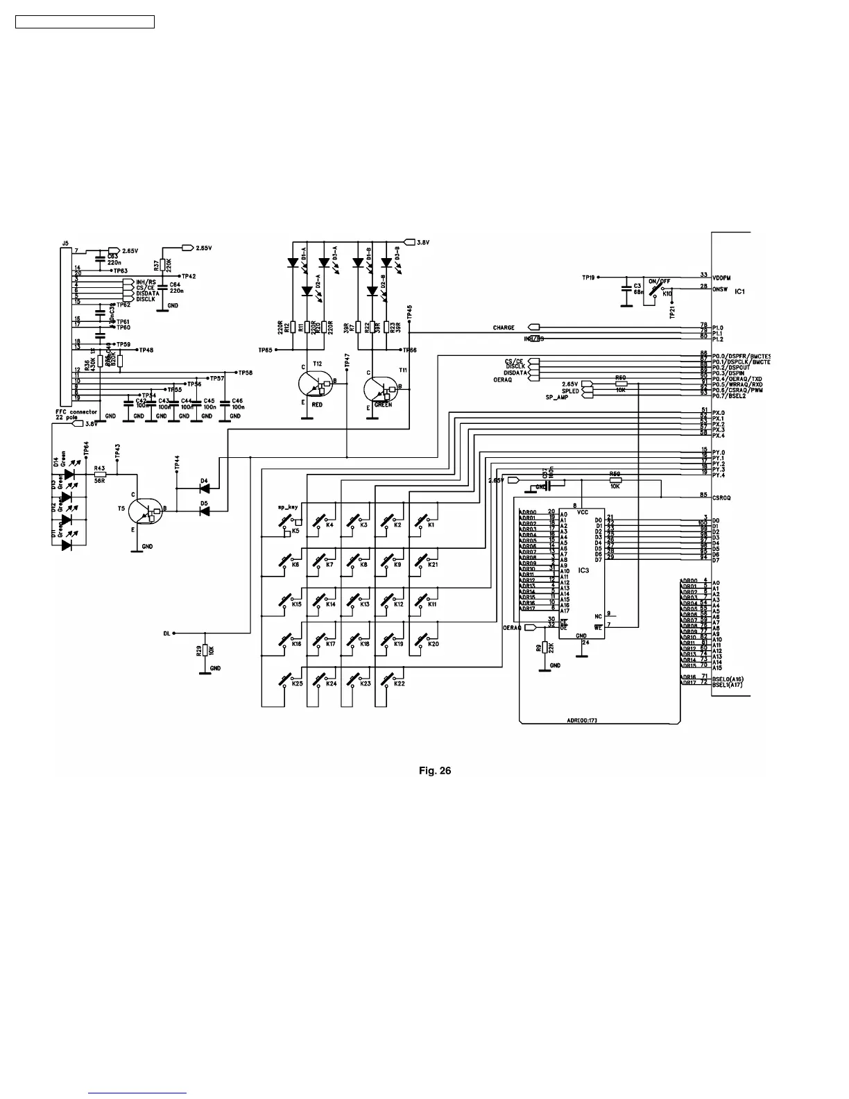
6.1.9. KEYBOARD (SEE Fig. 26)
The keyboard “On” button is connected directly to pin 33 and 28 of the BBIC. When pressed it turns the handset on and off.
All other keys are connected in a row/column matrix. They are scanned in five rows using scan pulses (only active when keys
are pressed) from IC1 pins 15 to 19. The five key matrix columns are input to the BBIC on pins 51, 52, 53, 57 and 58.
6.1.10. LCD DISPLAY, AND DISPLAY DRIVER (SEE Fig. 26)
The LCD display receives data via a serial interface. Serial data is sent to the display on pin 6 of the J5 socket, with control lines
at pin3 thru 6.
Circuit Diagram
28
KX-TCD705RUM / KX-TCD705RUS