(All schematic diagrams may be modified at any time with
the development of new technology)
Notes:
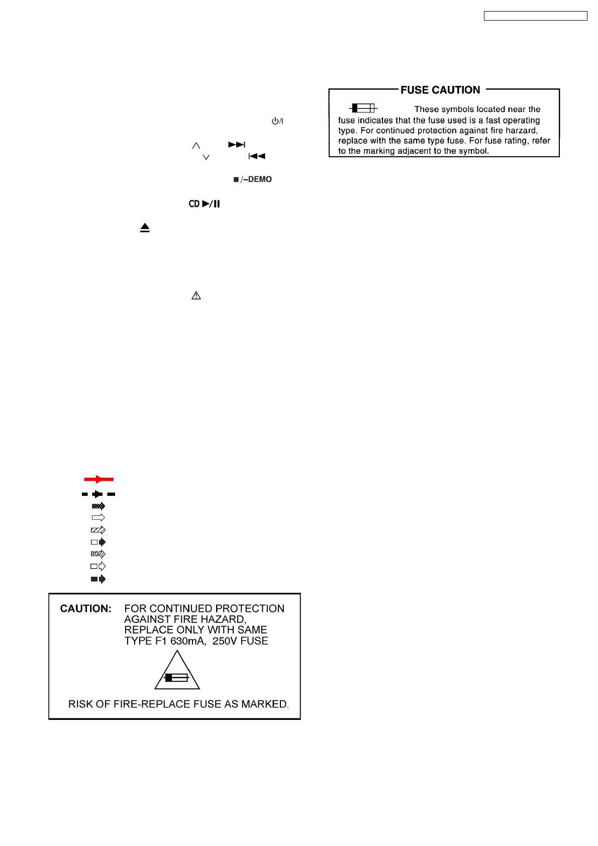
S900: POWER switch. (Standby / ON
).
S901: BASS/TREBLE switch.
S902: /FF/ switch. (
/FF/ ).
S903: /REW/ switch. (
/ REW / ).
S904: MUSIC PORT switch.
S905: STOP/-DEMO switch. (
)
S906: TUNER/BAND switch.
S907: CD switch. (
)
S1000: CD EJECT switch. (CD OPEN/CLOSE
)
S7201: RESET switch.
VR900: VR Volume jog.
·
Importance safety notice :
Components identified by
mark have special
characteristics important for safety.
Furthe rmore, special parts which have purposes of fire-
retardant (resistors), high-quality sound (capacitors), low-
noise (resistors), etc. are used.
When replacing any of components, be sure to use only
manufacturer´s specified parts shown in the parts list.
·
Capacitor values are in microfarad(µF ) unless specified
otherwise, F=Farad, pF=Pico-Farad
Resistance values are in ohm(Ω), unless specified
otherwise, 1K=1,000Ω, 1M=1,000KΩ
·
Voltage and Signal lines:
: +B Signal line
: -B Signal line
: CD-DA signal line
: CD signal line
: Main signal line
: FM/AM signal line
: AUX signal line
: FM signal line
: AM signal line
14 Notes Of Schematic Diagram
43
SA-PM4E / SA-PM4EB / SA-PM4EG