42
TH-103PF12E
1. Remove 2 screws and then remove AC Inlet Cover.
2. Disconnect the connector (P9).
3. Remove 3 screws and then remove the AC Inlet.
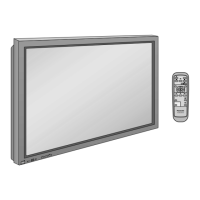
9.37. Removal of Front Glass, V1,
V3-Board and Cabinet Assy
1. Disconnect the connectors (DS15, P34).
2. Remove 2 screws ( ).
3. Remove 2 screws ( ) and then slide the Side Power Unit
upward.
4. Remove the Side Power Unit.
5. Remove 24 screws and then remove Cabinet Block.
6. Pull the bottom of the Cabinet Block forward and lift.
7. Remove the Cabinet Block.