INTRODUCTION
I-4
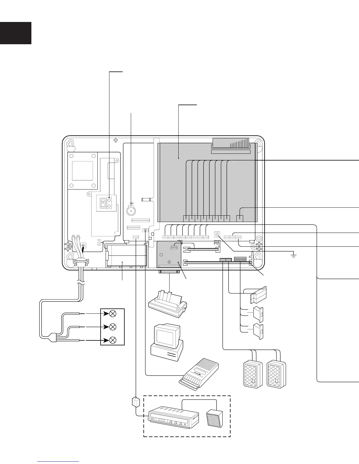
■ SYSTEM CONNECTION LAYOUT
Full system configuration layout.
Sensor
Earth Ground
(See page I-12)
Door opener A
Door opener B
(See page I-22)
Doorphone A Doorphone B
(VL-568G) (VL-568G)
Tape Recorder
or CD player
Paging SpeakerAmplifier
MOH
Personal
Computer
or
Serial Printer
Central Control
Unit (CCU)
External paging (See page I-33)
External Paging Adaptor
(See page I-33)
(See page I-32)
Built-in
Battery
Call Logging
I/F Card
(See page I-20)
Doorphone/Doorlatch
I/F Card (See page I-22)
Expansion Card
2 Exchange line/8 KT, 2 Exchange
line/8 SLT or 8 SLT (See page I-16)
FG
Only red lights: the CCU is the standby status
Green and red light: the CCU is the operating status
Only green lights: the status that the CCU is operating with the backup battery
FG1
Blue
Brown
Green-and-Yellow
(See page I-8)
N
L
E
Fuse spur
outlet
(See page I-31)
Lithium Battery
(See page I-31)