CONNECTION OF OPTIONAL UNITS
I-22
■ DOORPHONE/DOORLATCH I/F CARD
● Doorphone/Doorlatch I/F Card Specifications
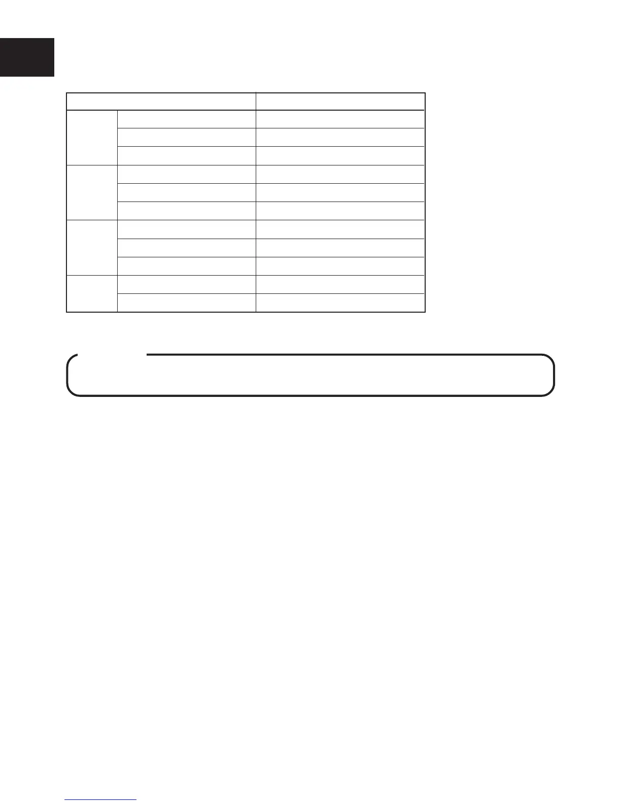
Table 4. Specifications
Item Description
Doorphone Number of connected units 2
Loop resistance 20 Ohms
Ringing tone 2 Types (Chime, tremolo)
Door opener Number of outputs 2
(relay)
Contact capacity Max. DC 24V, 1A
Modes 3 Modes (Door opener, multi, ringer)
Sensor Type Non-voltage
Detection time 250m Seconds, MIN (10mA)
Ringing tone Siren (settable)
Others Power supply 24V Supplied from CCU
Current consumption 20mA
● Installing the Doorphone/Doorlatch I/F Card
WARNING
Always unplug the AC plug from the outlet and power off the switch (STD BY) of the CCU
when mounting the Doorphone/Doorlatch I/F card.
q Align the Doorphone/Doorlatch I/F Card with the installation groove on the CCU, and insert
until the Doorphone/Doorlatch I/F Card is locked by the claws on the CCU.
w Insert the connector from the Doorphone/Doorlatch I/F Card into CN4 on the CCU.
● Connecting the Doorphone
Two Doorphones can be connected by using a DDK connector.
q Connect Doorphone A to pin Nos.1 and 2 of the DDK connector, and Doorphone B to pin Nos.
3 and 4.
w Connect the DDK connector to CN2 on the Doorphone I/F Card.
e Attach the EMI filter to the cable.
● Connecting the Sensor
A Sensor can be connected by using a DDK connector.
q Short-circuit the pins Nos.1 and 2 of the DDK connector.
w Connect Sensor+ to pin No.3 of the DDK connector and Sensor- to pin No.4.
e Connect the DDK connector to CN4 on the Doorphone/Doorlatch I/F Card.
● Connecting the Door Opener
Up to two Door Openers can be connected.
q Connect the leads from Door Opener A to the C (Common) and M (Make) terminals of CN3
Door Opener-A on the Doorphone/Doorlatch I/F Card.
w In the same way, connect the leads from Door Opener B to the C (Common) and M (Make)
terminals of CN3 Door Opener-B on the Doorphone/Doorlatch I/F Card. Put the cables to-
gether into the cable clamp.
NOTE : • When connecting the leads to the terminals of CN3 on the Doorphone/Doorlatch I/F Card, press the connector
knob using a screwdriver to insert the lead. Return the connector knob to secure the lead in place.
• Method or time of control can be set using Program. (See MODE 1 System 0502# to 0505# of Programming
Manual.)