WALL MOUNTING OF KEY TELEPHONES
I-15
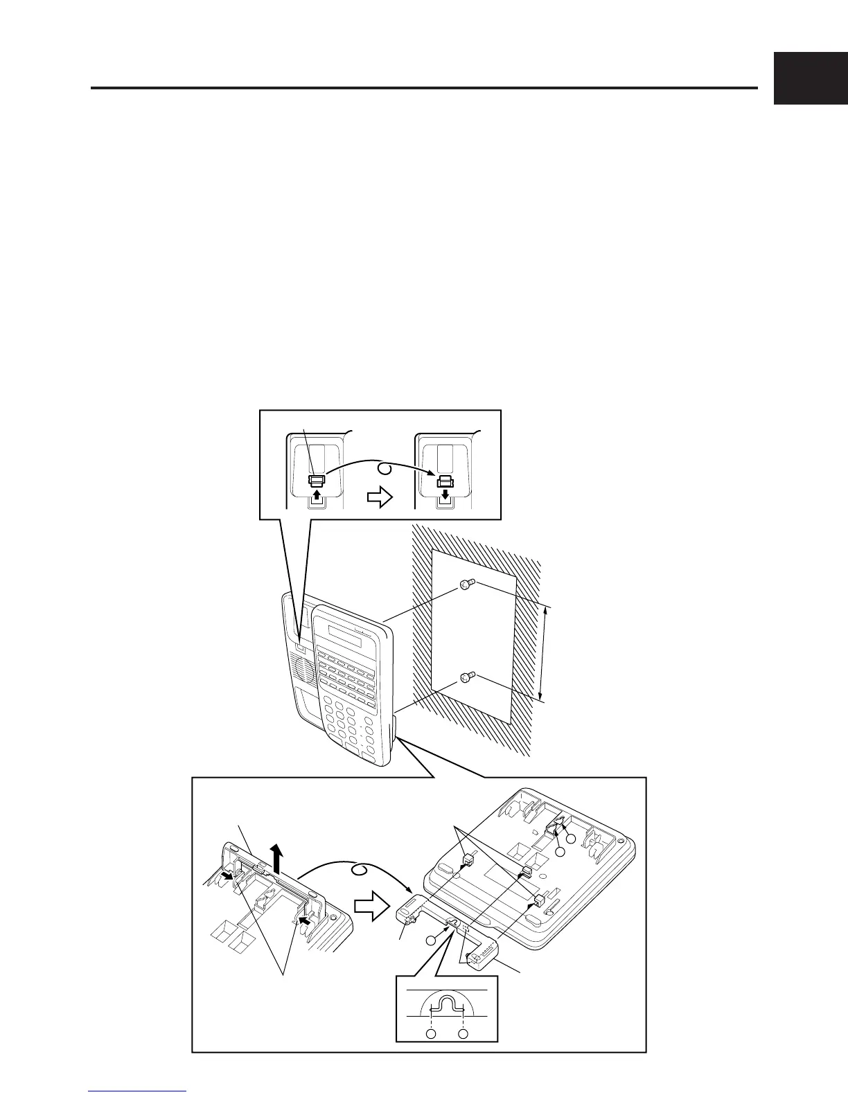
3. WALL MOUNTING OF KEY TELEPHONES
Install the key telephone on the wall according to the following procedure.
DSS console can be installed by the following procedure too.
q Remove the handset guide with a small screwdriver, turn it over, and reinsert it into the tel-
ephone.
w Press the Stand releases in toward the middle of the telephone to release the Desk stand.
e Cut parts a of the Desk stand with electrical wire cutters, and prepare wall mounting holes.
r Attach the Desk stand to the bottom of the telephone by aligning the tabs and tab guides, and
sliding the Desk stand into place.
t Attach two screws at the wall mounting positions (at 100 mm or 83 mm intervals), and secure at
mounting holes A-B or A-C on the Key telephone.
NOTE : • When securing at mounting holes
AA
AA
A-
BB
BB
B, the pitch between screws should be 100 mm.
• When securing at mounting holes
AA
AA
A-
CC
CC
C, the pitch between screws should be 83 mm.
Handset guide
100mm
or
83mm
Desk stand
Stand
releases
Desk stand
Tab
Tab
a
A
B
C
Tab guides
a
q
t
rt
e
w