INSTALLATION OF CCU
I-11
Extension connector CN2
LA
3
BH
1234
LABH
1234
LABH
DDK connector
LA
2
BH LA
1
BH
EXT. 10
EXT. 11
CCU
6
1
Secondary Socket (LJU)
1
2
3
6
5
4
2(B)
4(L)
3(H)
5(A)
6
1
Secondary Socket (LJU)
1
2
3
6
5
4
2(B)
4(L)
3(H)
5(A)
To telephone
Socket
To telephone
Socket
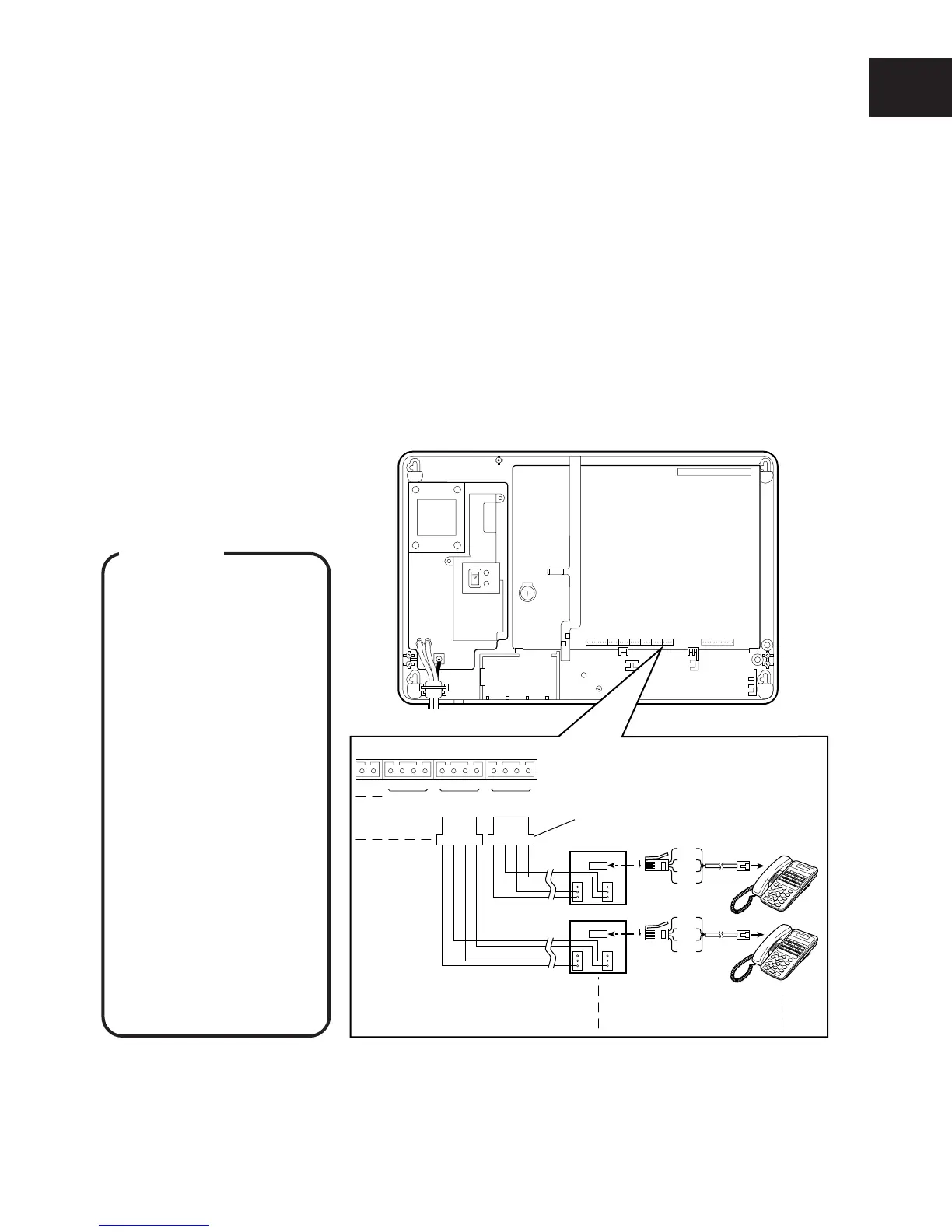
■ CONNECTION OF INTERNAL LINES
Eight internal lines can be connected to the 416 system at initial mounting.
NOTE : Installing the optional expansion card allows up to 16 lines to be connected to the 416 system. (See page I-20.)
Connect the internal line to the CCU using a DDK connector cable and a secondary socket (LJU).
q Connect the internal line “L”, “A”, “B” and “H” lines to pin Nos. 1, 2, 3 and 4 of the DDK
connector.
w Connect to EXT.1 of the Extension connector on the CCU.
e Connect the “L”, “A”, “B” and “H” lines from the DDK connector to the “3”, “5”, “2” and “4”
terminals of the secondary socket (LJU).
r Connect Key Tel.10 to the modular jack of the secondary socket (LJU).
t In the same way, connect Key Tel.11 to Key Tel.17 to the extension connector of EXT.2 to
EXT.8 on the CCU.
NOTE : Connect the administrator’s telephone on which programming is performed to EXT.10 (at initial setting).
WARNING
• Use a plier for tighten-
ing wires to DDK
connectors to prevent
from loose wiring.
• Do not leave any of
the internal lines
outside because
lightning may cause
serious damage to the
system. But, if you
install in any reason,
use protectors.
• Do not bundle internal
lines and AC power
line or exchange lines
together outside the
CCU. Distance of
50cm is required
between them to
assure proper func-
tioning.
NOTE : In this manual “T” and “R” on the PCB have been replaced with “A” and “B”, respectively, in the description.
 Loading...