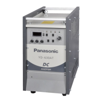
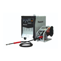
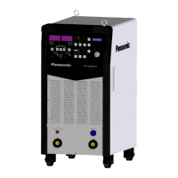
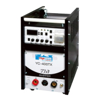
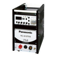
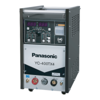
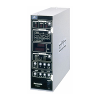
Names and functions
16
●
When Mode selection key
○
12
is set to “ Weld ”, (refer to description in
○
3
)・ when
key
○
3
selects different options, please adjust corrosponding set value according
different items.
・ During welding, “ Welding ” current can be adjusted. However “ initial ” and
“ crater ” current can NOT be changed.
●
When Mode selection key
○
12
is set to “F. Adj”,( Section 5.4) ・ refer to
detailed description.
●
When Mode selection key
○
12
is set to “ Call ”,
・ It does not function.. ( When“ Call ” is selected, only Jog-dial ○
7
, key ○
8
, ○
10
, ○
12
work. )
●
When Mode selection key ○
12
is set to “ Record ”,
・ It does not function.. (When “ Call ” is selected, only Jog-dial
○
7
, key
○
8
,
○
10
,
○
12
work. )
voltage display
7-segment LED
●
When Mode selection key ○
12
is set to “ Weld ”,
・ On stand-by status,
○
6
data of the item being selected is shown.
・ During welding, it shows the voltage value of the actual output.
●
When Mode selection key ○
12
is set to “F. Adj”, ( Section 5.4)
・ It shows specific set values.
●
When Mode selection key ○
12
is set to “ Call ”,( Section 5.6)
・ Use Jog-dial ○
7
to select channel number. LED shows corresponding channel
number. If the welding parameters are avilable in the channel, the channel can be
selected, else the corresponding channel can NOT be selected. When the channel
stored with data is selected, the channel and parameters are displayed alternately
and welding can start.
●
When Mode selection key
○
12
is set to “ Record ”, ( Section 5.6)
・ By turning the Jog-dial
○
7
, channel number can be selected. LED shows “CH”
setting current and voltage. The flashing means welding parameters to be stored.
・ Press selection key ○
12
to return to “ Weld ” from “ Record ” and the corresponding
parameters are recorded in the channel being selected.
●
When a self-diagnosable error occurs, ( For troubleshooting: Section 13.1)
・ It shows alarm signal number.
setting
“ voltage ”
“ arc length ”
“ arc
characteristics ”
“ penetration
control ”
function select
●
When “voltage”/ “arc length ” function is selected, the setting method of the
corrosponding selection number is decided by P11 of “F. Adj” function menu.
When P11 is 0, it is adjusted by wire feeder potentiometer; when P11 is 1, it can
be changed by Jog-dial ○
7
●
When“ arc characteristics ” function is selected, the value can be changed by Jog-
dial ○
7
●
When“penetration control ” function is selected, the value can be changed by Jog-
dial ○
7
Note: To change“penetration control ”, welding method ○
14
is to be selected as
“Deepen ”.
●
When Mode selection key ○
12
is set to“ Weld ”, (please refer to the description in
○
6
)
・ When key ○
6
selects different options, please adjust corrosponding set value
according different items.
・ During welding, the contents in
○
8
can be adjusted. However, “ initial ” and
“ crater ” current change not be changed.
●
When Mode selection key ○
12
is set to “F. Adj”, ( Section 5.4)
・ Refer to detailed description.
●
When Mode selection key
○
12
is set to “ Call ”,
・ select Call channel number. (Only the channel number being recorded in
○
5
can
be shown. )
●
When Mode selection key
○
12
is set to “ Record ”,
・ Record channel number is select.