Maintenance 3-1
AC10 Inverter
Chapter 3 Installation
IMPORTANT Read Chapter 14 “Compliance” before installing this unit.
3.1 Equipment Precautions
• Check for signs of transit damage.
• Check the product code on the rating label conforms to your requirements.
• Installation and application environment should be free of rain, drips, steam, dust and oily
dirt; without corrosive or flammable gases or liquids, metal particles or metal powder.
Environment temperature within the scope of -10℃~+50℃ (40℃ without derating)
• Please install inverter away from combustibles.
• Do not drop anything into the inverter.
• The reliability of inverters relies heavily on the temperature. As the surrounding
temperature increases by 10 degrees the inverter life will be halved.
• The inverter is designed to be installed in a control cabinet, smooth ventilation should be
ensured and the inverter should be installed vertically. If there are several inverters in one
cabinet, in order to ensure ventilation, install inverters side by side. If it is necessary to
install several inverters above each other, you need additional ventilation.
• Never touch the internal elements for 15 minutes after power goes off. Wait until it is
completely discharged.
• Input terminals L1/R, L2/S and L3/T are connected to power supply of 400V/230V (L1, L2
are connected to 230V) while output terminals U, V and W are connected to motor.
• Proper grounding should be ensured with grounding resistance not exceeding 4Ω; separate
grounding is required for motor and inverter. Grounding with series connection is forbidden.
• There should be separate wiring between control loop and power loop to avoid any
possible interference.
• Cable length should be minimized to limit common mode interference.
• If circuit breaker or contactor needs to be connected between the drive and the motor, be
sure to operate these circuit breakers or contactor when the drive has no output, to avoid
damaging the drive.
• Before using the drive, the insulation of the motors must be checked, especially if it is used for
the first time or if it has been stored for a long time. This is to reduce the risk of the drive being
damaged by poor insulation of the motor.
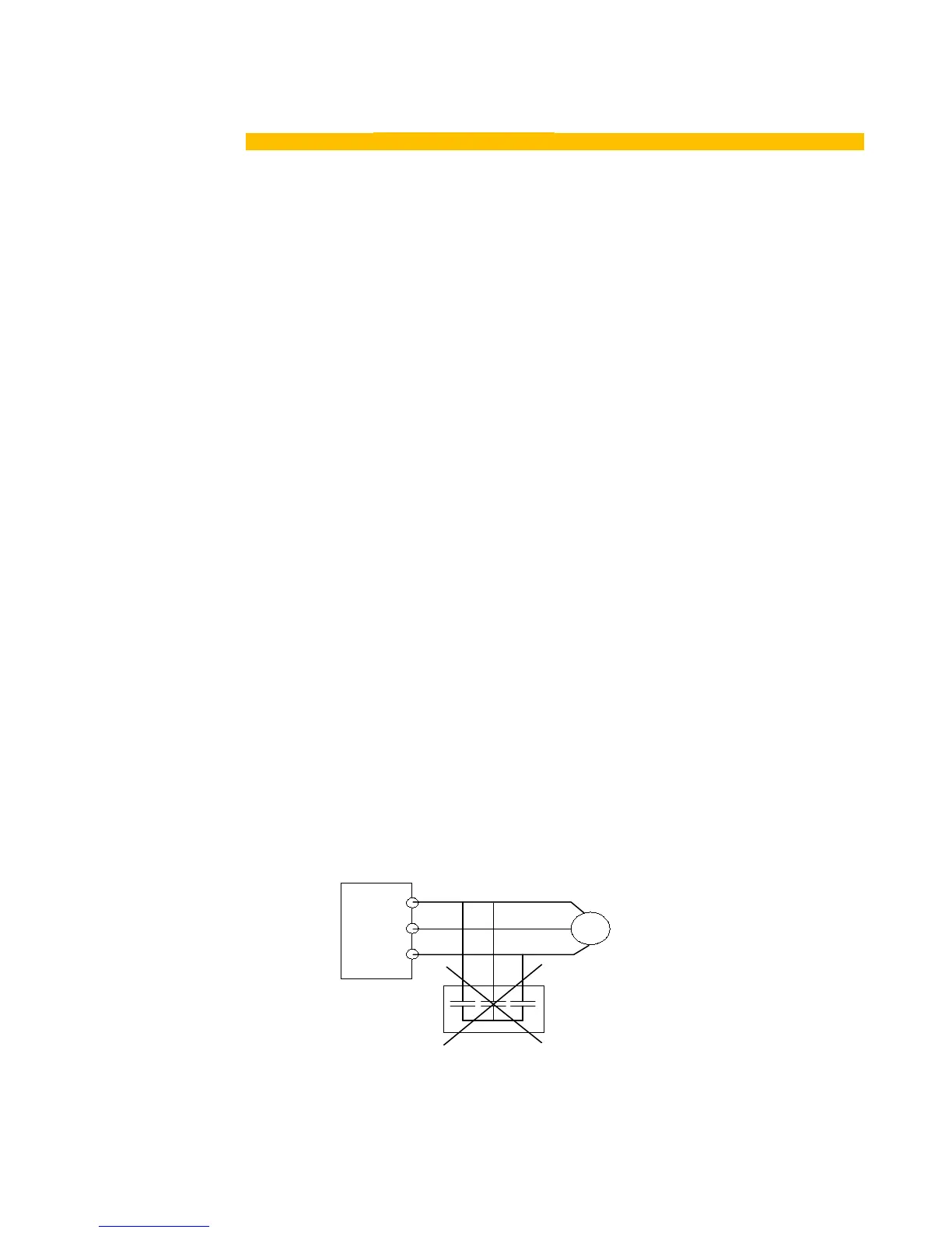
• Do not connect any varistor or capacitor to the output terminals of the drive because the drive’s
output voltage waveform is pulse wave, otherwise tripping or damaging of components may
occur.

 Loading...


