Operation and Simple Running 8-8
AC10 Inverter
8.3.4 Setting the frequency with analog terminal and controlling the
operation with control terminals
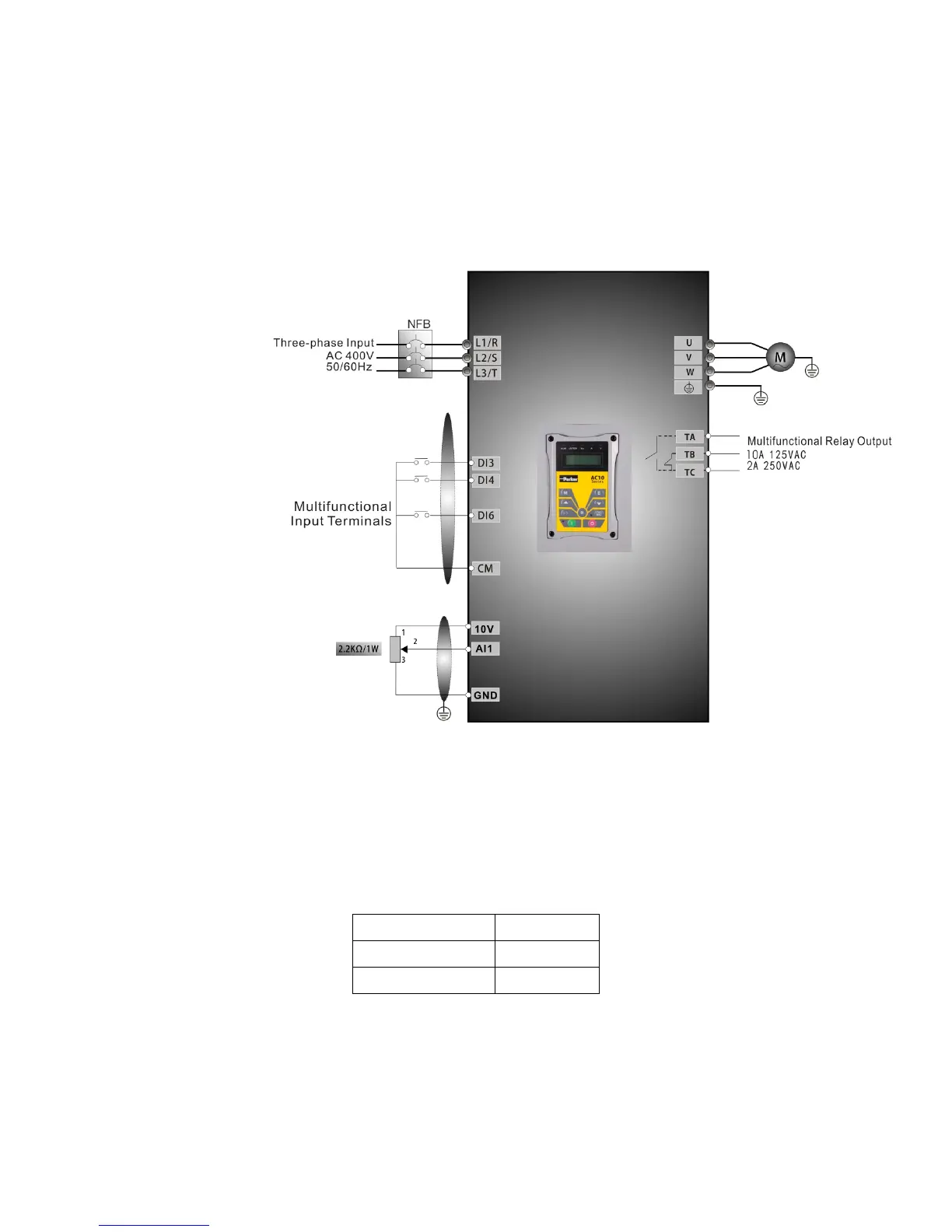
i. Connect the wires in accordance with
Figure 8-3. After having checked the wiring
successfully, switch on the mains supply, and power on the inverter. Note: 2K~5K
potentiometer may be used for setting external analog signals. For the cases with
higher requirements for precision, a precise multiturn potentiometer is
recommended, and adopt shielded wire for the wire connection, with near end of
the shielding layer grounded reliably.
Figure 8-3 Wiring Diagram 3
ii. Press the “M” key, to enter the programming menu.
iii. Study the parameters of the motor: the operation process is the same as that of
example 1. (Refer to 8.3.1 for tuning of the motor).
iv. Set functional parameters of the inverter:
Function code Values
F203 1
F208 1
v. (5) There is a red two-digit coding switch SW1 near the control terminal block, as
shown in Figure 4-4. The function of coding switch is to select the voltage signal
(0~5V/0~10V) or current signal of analog input terminal AI2, current channel is
default. In actual application, select the analog input channel through F203. Turn
switches 1 to ON and 2 to ON as illustrated in the figure, and select 0~20mA
current speed control. Other switches state and mode of control speed are shown
in table
Table 8-2.

 Loading...


