Installation & Connection 7-1
AC10 Inverter
Chapter 7 Installation & Connection
7.1 Installation
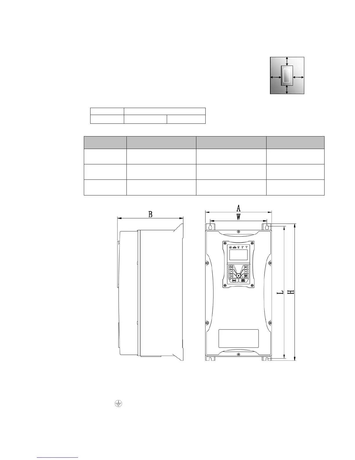
Inverter should be installed vertically, as shown in Figure 7-1. Sufficient
ventilation space should be ensured in its surrounding.
Clearance dimensions (recommended) are available from Table 7-1
Clearance Dimensions for installing of the inverter. Space between 2
drives 25mm.
Table 7-1 Clearance Dimensions
Frame
External Dimension
A×B×H (H1) mm
Mounting Size(W×L) Mounting Bolt
1
200×198×412 171×398 M5
2 242×198×418 215×402 M6
3
242×228×471 210×454 M8
.
Cover Layout
7.2 Connection
Connect R/L1, S/L2 and T/L3 terminals (L1/R and L2/S terminals for single-phase) with power
supply, to grounding, and U, V and W terminals to motor.
Motor shall have to be grounded. Otherwise electrified motor causes interference.
For inverter power lower than 15kW, braking cell is also built in. If the load inertia is moderate,
it is OK to only connect braking resistance.
Figure 7-1 Installation Sketch
TC-Hydraulik - Rsdorfer Str. 8 - 25746 Heide - Lars Lornsen - T: +49 481 909 - 34 - l.lornsen@tc-hydraulik.de - www.tc-hydraulik.de

 Loading...


