Installation & Connection 7-7
AC10 Inverter
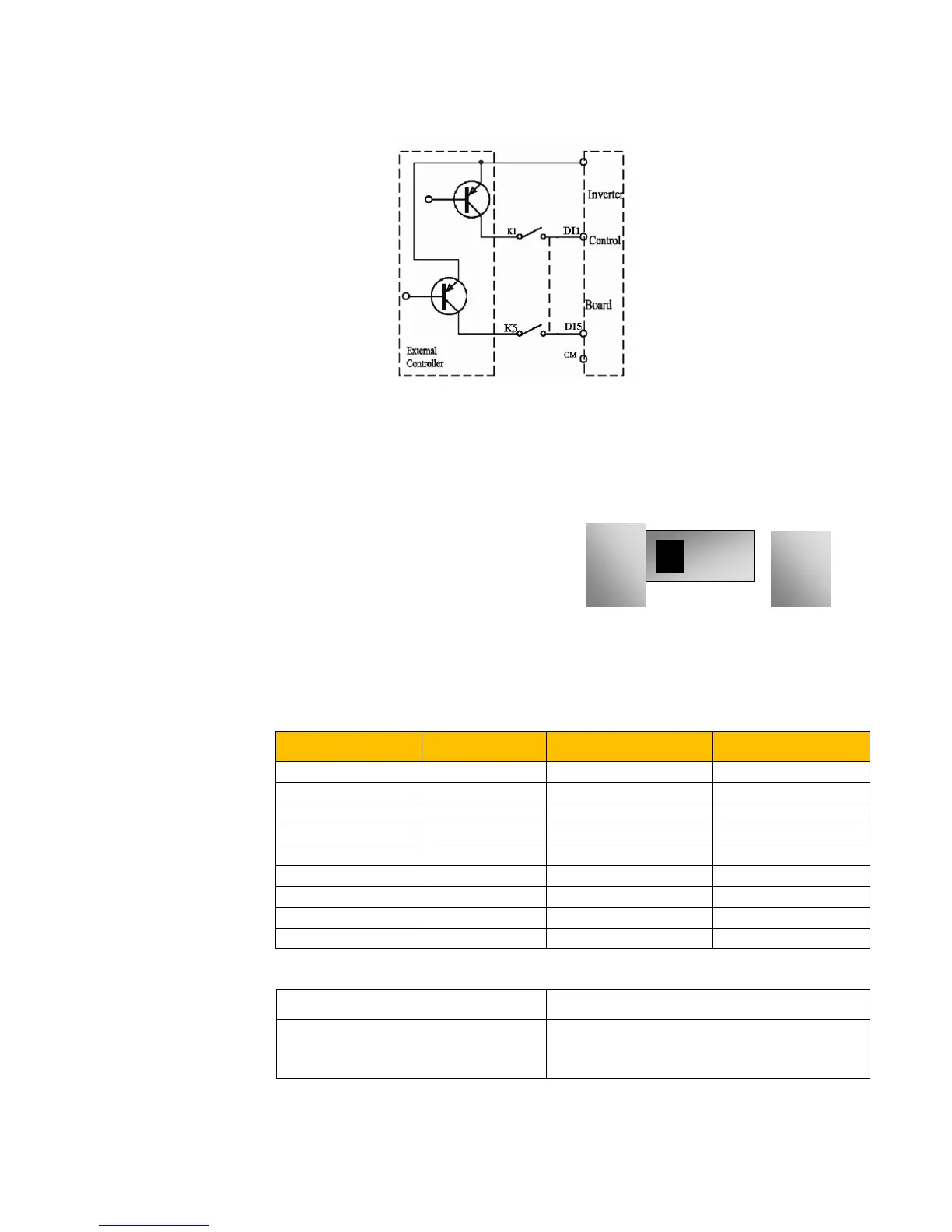
7.5.4 Wiring for active drain electrode (PNP mode)
Wiring by source electrode is a mode most in use at present. Wiring for control terminal is
connected by source electrode, user should choose wiring mode according to requirement.
Instructions of choosing NPN mode or PNP mode:
1. There is a toggle switch J7 near to control
terminals. Please refer to Figure 7-2.
2. When turning J7 to “NPN”, DI terminal is
connected to CM.
Figure 7-2 Toggle Switch J7
When turning J7 to “PNP”, DI terminal is connected to 24V.
7.5.5 Recommended Wiring
Inverter Model
7.5.6 Lead Section Area of Protect Conductor ( Grounding Wire)
Lead section area S of U,V,W (mm
2
) Minimum lead section area S of E (mm
2
)

 Loading...


