Function Parameters 9-11
AC10 Inverter
9.2 Operation Control
F200
Source of start command
0: Keypad command;
1: Terminal command;
2: Keypad+Terminal;
3: MODBUS;
Mfr’s
value: 4
F201
Source of stop command
0: Keypad command;
1: Terminal command;
2: Keypad+Terminal;
3: MODBUS;
Mfr’s
value: 4
F200 and F201 are the resource of selecting inverter control commands.
Inverter control commands include: starting, stopping, forward running, reverse running,
jogging, etc.
”Keypad command” refers to the start/stop commands given by the “I” or “O” key on the keypad.
“Terminal command” refers to the start/stop command given by the “I” terminal defined by
F316-F323.
When F200=3 and F201=3, the running command is given by MODBUS communication.
When F200=2 and F201=2, “keypad command” and “terminal command” are valid at the mean
time, F200=4 and F201=4 are the same.
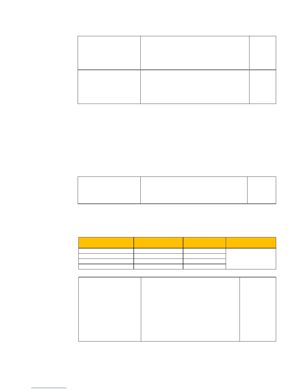
F202
Mode of direction setting
0: Forward running locking;
1: Reverse running locking;
2: Terminal setting
Mfr’s
value: 0
The running direction is controlled by this function code together with other speed control mode
which can set the running direction of inverter. When auto-circulation speed is selected by
F500=2, this function code is not valid.
When speed control mode without controlling direction is selected, the running direction of
inverter is controlled by this function code, for example, keypad controls speed.
F203
Main frequency source X
0: Memory of digital given;
1: External analog AI1;
2: External analog AI2;
3: Pulse input given;
4: Stage speed control;
5: No memory of digital given;
6: Reserved;
7: Reserved;
8:Reserved;
9: PID adjusting; 1
Mfr’s value: 0
Main frequency source is set by this function code.
0: Memory of digital given
Its initial value is the value of F113. The frequency can be adjusted through the key “up” or
“down”, or through the “up”, “down” terminals.
Direction given by F202
Direction given by
other control mode
Running direction Remarks
0 means forward.
1 means reverse.
TC-Hydraulik - Rsdorfer Str. 8 - 25746 Heide - Lars Lornsen - T: +49 481 909 - 34 - l.lornsen@tc-hydraulik.de - www.tc-hydraulik.de

 Loading...


