9-10 Function Parameters
AC10 Inverter
F154 Automatic voltage
rectification
2:Invalid during deceleration process
Mfr’s value: 0
This function is enabled to keep output voltage constant automatically in the case of fluctuation
of input voltage, but the deceleration time will be affected by internal PI adjustor. If deceleration
time is forbidden being changed, please select F154=2.
F155 Digital secondary frequency setting
Mfr’s value: 0
F156 Digital secondary frequency polarity setting
F157 Reading secondary frequency
F158 Reading secondary frequency polarity
Under combined speed control mode, when secondary frequency source is digital setting memory
(F204=0), F155 and F156 are considered as initial set values of secondary frequency and polarity
(direction).
In the mode of combined speed control, F157 and F158 are used for reading the value and direction
of secondary frequency.
For example, when F203=1, F204=0. F207=1, the given analog frequency is 15Hz, inverter is
required to run to 20Hz. In case of this requirement, user can push “UP” button to raise the frequency
from 15Hz to 20Hz. User can also set F155=5Hz and F160=0 (0 means forward, 1 means reverse). In
this way, inverter can be run to 20Hz directly.
F159 Random carrier-wave selection
Mfr’s value: 1
When F159=0, inverter will modulate as per the carrier-wave set by F153. When F159=1, inverter will
operate in mode of random carrier-wave modulating.
Note: when random carrier-wave is selected, output torque will increase but noise will be loud. When
the carrier-wave set by F153 is selected, noise will be reduced, but output torque will decrease.
Please set the value according to the situation.
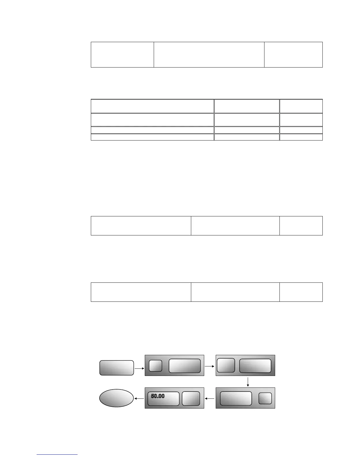
F160 Reverting to manufacturer values
Mfr’s value: 0
When there is problem with inverter’s parameters and manufacturer values need to be restored,
set F160=1. After “Reverting to manufacturer values” is done, F160 values will be automatically
changed to 0.
“Reverting to manufacturer values” will not work for the function-codes marked “○”in the
“change” column of the parameters table. These function codes have been adjusted properly
before delivery. It is recommended not to change them.
Figure 9-5 Reverting to Manufacturer Values
TC-Hydraulik - Rsdorfer Str. 8 - 25746 Heide - Lars Lornsen - T: +49 481 909 - 34 - l.lornsen@tc-hydraulik.de - www.tc-hydraulik.de

 Loading...


