EasyManuals Logo

Parker AC10 series User Manual

Parker AC10 series
145 pages
To Next Page IconTo Next Page
To Previous Page IconTo Previous Page
Page #25 background imageLoading...
Page #25 background image
Installation & Connection 7-3
AC10 Inverter
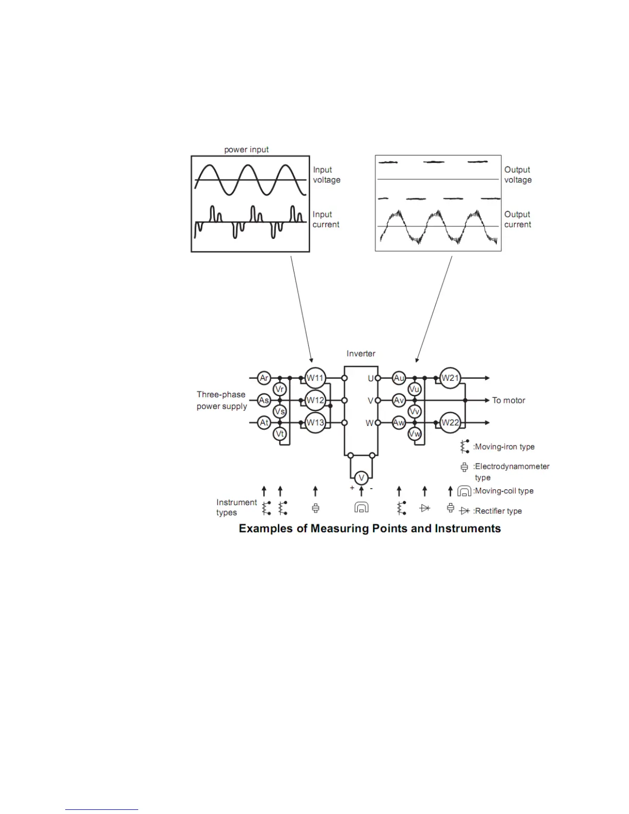
7.3 Measurement of Main Circuit Voltages, Currents and Powers
Since the voltages and currents on the inverter power supply and output sides include
harmonics, measurement data depends on the instruments used and circuits measured. When
instruments for commercial frequency are used for measurement, measure the following
circuits with the recommended instruments.
TC-Hydraulik - Rsdorfer Str. 8 - 25746 Heide - Lars Lornsen - T: +49 481 909 - 34 - l.lornsen@tc-hydraulik.de - www.tc-hydraulik.de

Table of Contents

Other manuals for Parker AC10 series

Questions and Answers:

Question and Answer IconNeed help?

Do you have a question about the Parker AC10 series and is the answer not in the manual?

Parker AC10 series Specifications

General IconGeneral
Overload Capacity150% for 60 seconds
Analog Inputs2
Analog Outputs1
Communication OptionsModbus RTU
Protection RatingIP20
Input Voltage200-240VAC, 380-480VAC, 500-575VAC, 600VAC, 690VAC
Digital Outputs2
ProtectionOvercurrent, Overvoltage, Undervoltage, Overtemperature, Short Circuit
Operating Temperature-10°C to +50°C
Humidity5% to 95% (non-condensing)
DimensionsVaries by model
WeightVaries by model
BrakingBuilt-in dynamic braking

Related product manuals