7-2 Installation & Connection
AC10 Inverter
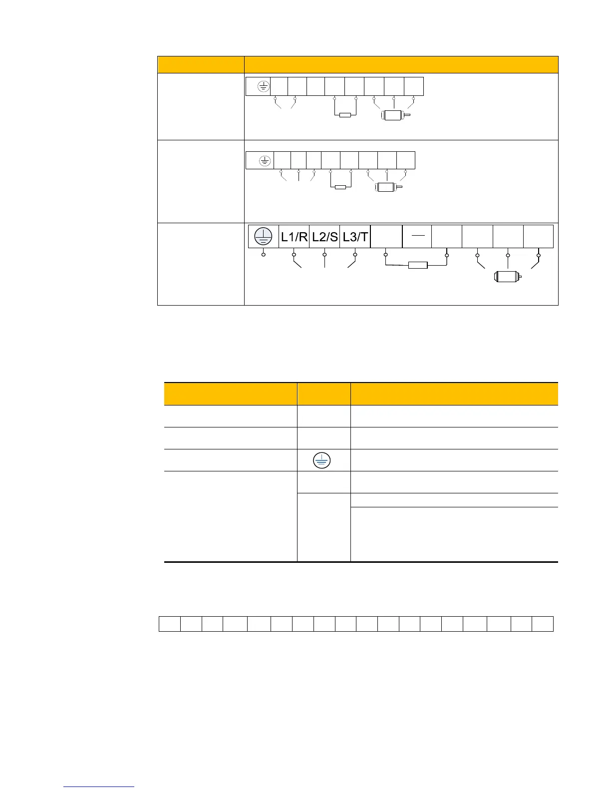
Model Sketch
1-phase 230V
0.4kW~2.2kW
3-phase 230V
0.4kW~2.2kW
3-phase 400V
0.4kW~15kW
Note: power terminals L1, L2 of single-phase 230V 0.4-2.2kW are connected to 230V of power
grid;
Introduction of terminals of power loop
Terminals
Terminal Function Description
Power Input Terminal
Input terminals of three-phase 400V AC voltage
(R/L1 and S/L2 terminals for single-phase)
Inverter power output terminal, connected to
motor.
Inverter grounding terminal.
Braking Terminal
P, B
External braking resistor (Note: no Terminals P
or B for inverter without built-in braking unit).
External connections to optional braking unit
P connected to input terminal “P” or “DC+”of
braking unit,
- connected to input terminal of braking unit “N”
Control loop terminals as follows:
TA TB TC D01 24V CM DI1
L
1
L
2
P/+
B
U V W
~220-240V
Braking
resistor
3-phase output
PE/
L
1
L
2
P/+
B
U V W
~220-240V
Braking
resistor
3-phase output
L
3
PE/
P U
V W
Braking resistor
~
400V
B
Grounding
Input
TC-Hydraulik - Rsdorfer Str. 8 - 25746 Heide - Lars Lornsen - T: +49 481 909 - 34 - l.lornsen@tc-hydraulik.de - www.tc-hydraulik.de

 Loading...


