EasyManua.ls Logo

Parker AC10 series

Parker AC10 series
145 pages
To Next Page IconTo Next Page
To Previous Page IconTo Previous Page
Loading...
8-9 Operation and Simple Running
AC10 Inverter
V
J
J5
+
-
S1
vi. Close the switch DI3, the motor starts forward running;
vii. The potentiometer can be adjusted and set during running, and the current setting
frequency of the inverter can be changed;
viii. During running process, switch off the switch DI3, then, close DI4, the running
direction of the motor will be changed;
ix. Switch off the switches DI3 and DI4, the motor will decelerate until it stops running;
x. Switch off the air switch, and power off the inverter.
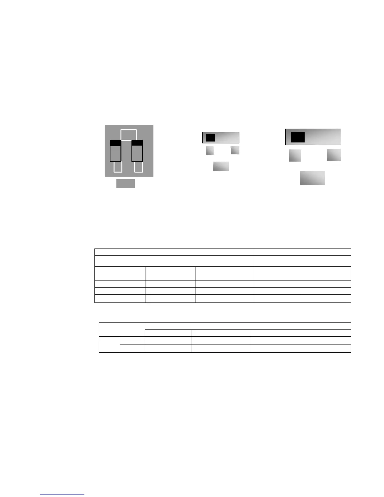
xi. Analog output terminal AO1 can output voltage and current signal, the selecting
switch is J5, please refer to
Figure 8-6 the output relation is shown in Table 8-3.
Figure 8-4 Figure 8-5 Figure 8-6
The Setting of Coding Switch and Parameters in the Mode of Analog Speed Control
Table 8-2
F203=2, channel AI2 is selected
F203=1, channel AI1 is selected
SW1 coding switch S1toggle switch
Coding Switch 1 Coding Switch 2
Mode of Speed
Control
+ -
OFF
OFF
0~5V voltage
0-10V voltage
-10-10V voltage
OFF
ON
0~10V voltage
ON
ON
0
20mA current
Table 8-3 The relationship between AO1 and J5 and F423
AO1 output
Setting of F423
0
1
2
J5
V
0
5V
0
10V
Reserved
I
Reserved
0
20mA
4
20mA
ON
2
1
SW1
TC-Hydraulik - Rsdorfer Str. 8 - 25746 Heide - Lars Lornsen - T: +49 481 909 - 34 - l.lornsen@tc-hydraulik.de - www.tc-hydraulik.de

Table of Contents

Other manuals for Parker AC10 series

Related product manuals