EasyManuals Logo

Parker AC10 series User Manual

Parker AC10 series
145 pages
To Next Page IconTo Next Page
To Previous Page IconTo Previous Page
Page #50 background imageLoading...
Page #50 background image
9-6 Function Parameters
AC10 Inverter
F127/F129 Skip Frequency A,B (Hz)
Setting range:
0.00
650.0
Mfr’s value:0.00Hz
F128/F130 Skip Width A,B (Hz)
Setting range:
±2.5
Mfr’s value: 0.0
Systematic vibration may occur when the motor is running at a certain frequency. This
parameter is set to skip this frequency.
The inverter will skip the point automatically when output frequency is equal to the set value of
this parameter.
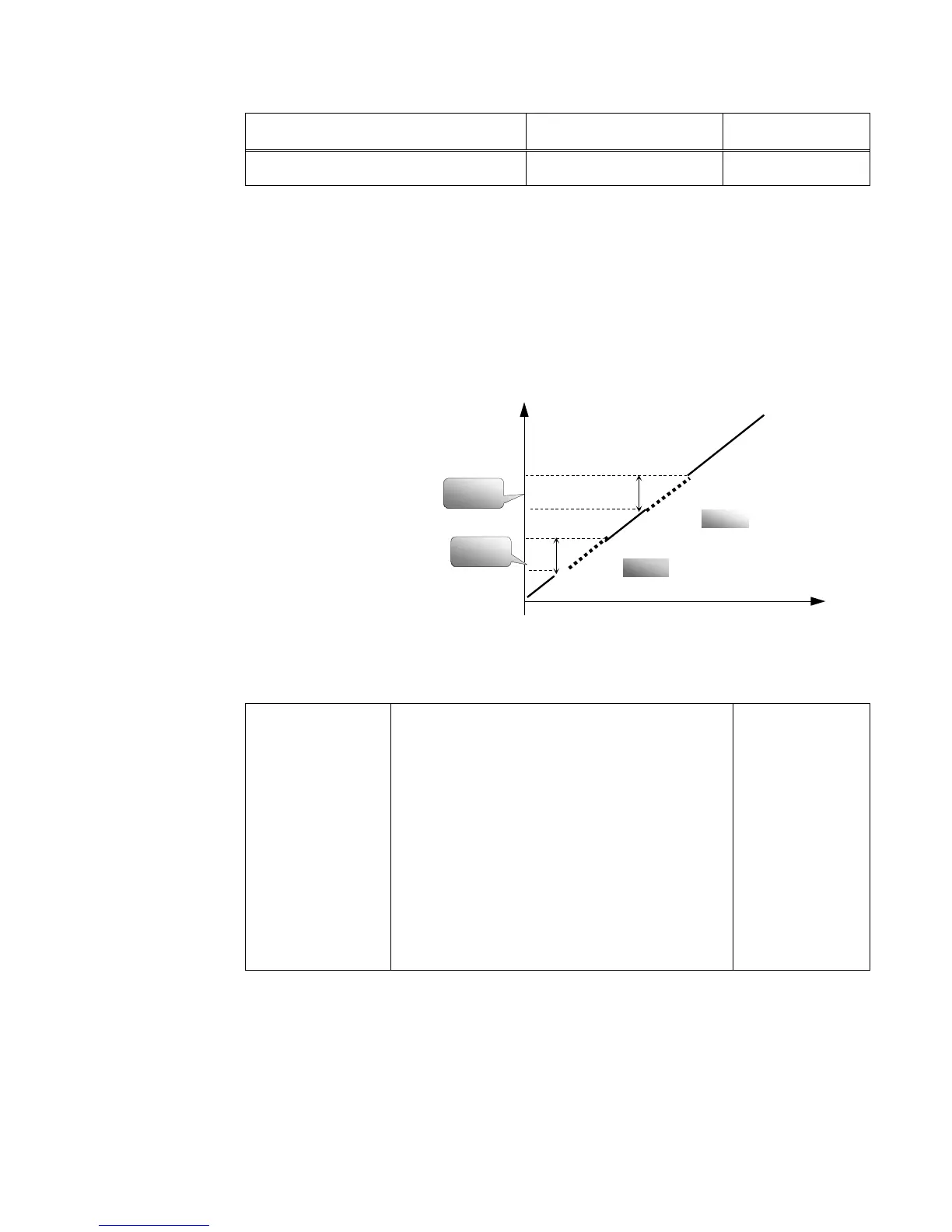
“Skip Width” is the span from the upper to the lower limits around Skip Frequency. For example,
Skip Frequency=20Hz, Skip Width=±0.5Hz, inverter will skip automatically when output is
between 19.520.5Hz.
Inverter will not skip this frequency span during acceleration/deceleration.
Note: During the
process of Flycatching,
skip frequency
function is invalid.
After Flycatching is
finished, this function
is valid.
Figure 9-2 Skip Frequency
F131 Running
Display Items
0
Current output frequency/function-code
1Output rotary speed
2Output current
4Output voltage
8PN voltage
16PID feedback value
32Temperature
64Reserved
128Linear speed
256PID given value
512Reserved
1024Reserved
2048Output power
4096
Output torque
Mfr’s value:
0+1248=15
Selection of one value from 1, 2, 4, 8, 16, 32, 64 and 128 shows that only one specific display
item is selected. Should multiple display items be intended, add the values of the corresponding
display items and take the total values as the set value of F131, e.g., just set F131 to be 19
(1+2+16) if you want to call “current output rotary speed”, “output current” and “PID feedback
value. The other display items will be covered.
As F1318191, all display items are visible, of which, “frequency/function-code” will be visible
whether or not it is selected.
Should you intend to check any display item for segment LCB just press the “M” key for
switchover.
Time (t)
Output FrequencyHz
F128
F130
F129
F127
TC-Hydraulik - Rsdorfer Str. 8 - 25746 Heide - Lars Lornsen - T: +49 481 909 - 34 - l.lornsen@tc-hydraulik.de - www.tc-hydraulik.de

Table of Contents

Other manuals for Parker AC10 series

Questions and Answers:

Question and Answer IconNeed help?

Do you have a question about the Parker AC10 series and is the answer not in the manual?

Parker AC10 series Specifications

General IconGeneral
Overload Capacity150% for 60 seconds
Analog Inputs2
Analog Outputs1
Communication OptionsModbus RTU
Protection RatingIP20
Input Voltage200-240VAC, 380-480VAC, 500-575VAC, 600VAC, 690VAC
Digital Outputs2
ProtectionOvercurrent, Overvoltage, Undervoltage, Overtemperature, Short Circuit
Operating Temperature-10°C to +50°C
Humidity5% to 95% (non-condensing)
DimensionsVaries by model
WeightVaries by model
BrakingBuilt-in dynamic braking

Related product manuals