EasyManuals Logo

Parker AC10 series User Manual

Parker AC10 series
145 pages
To Next Page IconTo Next Page
To Previous Page IconTo Previous Page
Page #52 background imageLoading...
Page #52 background image
9-8 Function Parameters
AC10 Inverter
F139 Square compensation
Setting range:
1: 1.5
2: 1.8
3: 1.9
4: 2.0
Mfr’s value: 1
When F106=2, the function of F137 is valid.
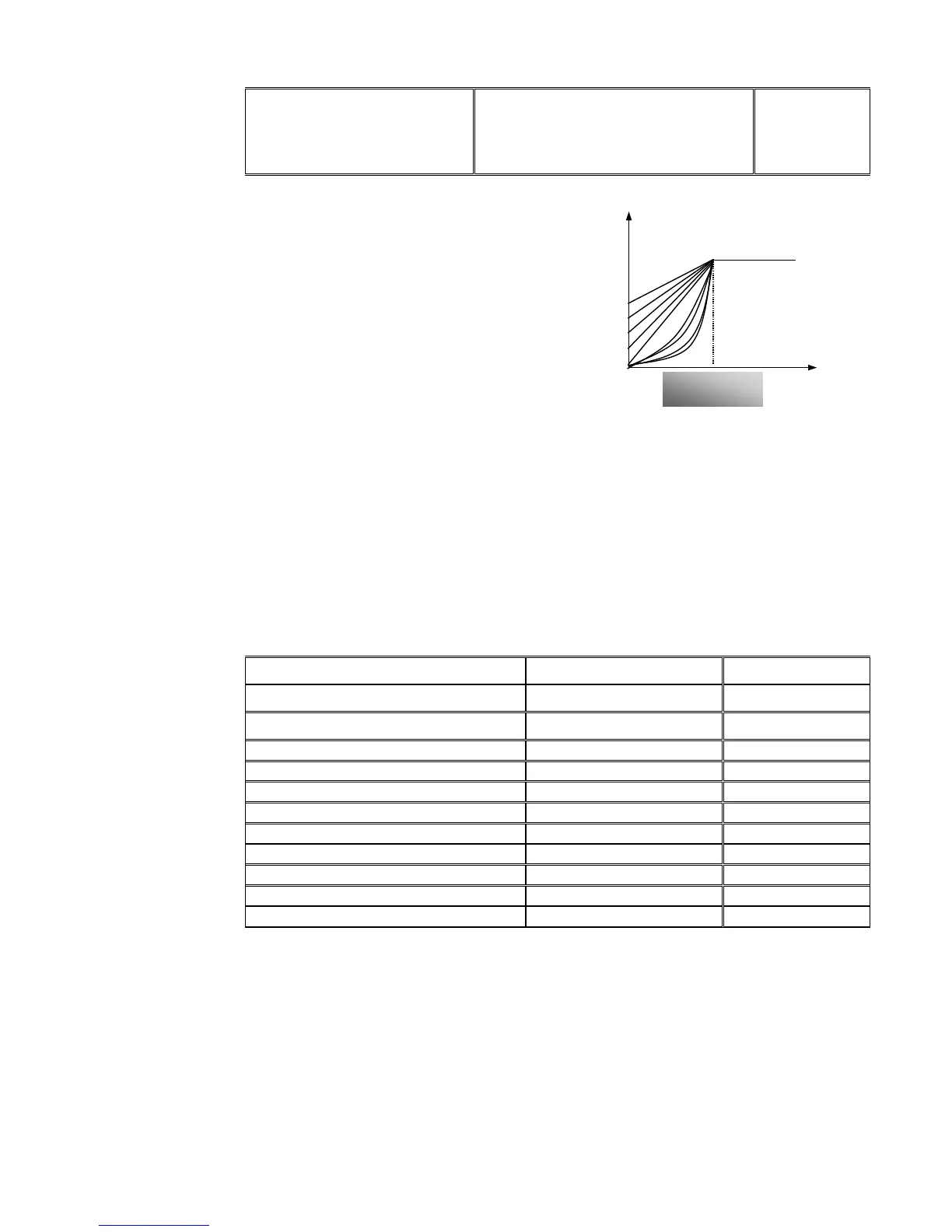
To compensate low-frequency torque controlled
by V/F, output voltage of inverter while
low-frequency should be compensated.
When F137=0, linear compensation is chosen
and it is applied on universal constant-torque
load;
When F137=1, square compensation is chosen
and it is applied on the loads of fan or water
pump;
When F137=2, user-defined multipoint
compensation is chosen and it is applied on the
special loads of spin-drier or centrifuge;
Figure 9-3 Torque Promotion
This parameter should be increased when the load is heavier, and this parameter should be
decreased when the load is lighter.
If the torque is elevated too much, the motor overheats easily, and the current of inverter will be
too high. Please check the motor while elevating the torque.
When F137=3, auto torque compensation is chosen and it can compensate low-frequency
torque automatically, to diminish motor slip, to make rotor rotary speed close to synchro rotary
speed and to restrain motor vibration. Customers should correctly set motor power, rotary
speed, numbers of motor poles, motor rated current and stator resistance. Please refer to the
chapter Operation process of measuring motor parameters”.
F140 User-defined frequency point F1
Setting range: 0F142
Mfr’s value: 1.00
F141 User-defined voltage point V1
Setting range: 0100
Mfr’s value: 4
F142 User-defined frequency point F2
Setting range: F140F144
Mfr’s value: 5.00
F143 User-defined voltage point V2
Setting range: 0
100
Mfr’s value: 13
F144 User-defined frequency point F3
Setting range: F142
F146
Mfr’s value: 10.00
F145 User-defined voltage point V3
Setting range: 0
100
Mfr’s value: 24
F146 User-defined frequency point F4
Setting range: F144
F148
Mfr’s value: 20.00
F147 User-defined voltage point V4
Setting range: 0
100
Mfr’s value: 45
F148 User-defined frequency point F5
Setting range: F146
F150
Mfr’s value: 30.00
F149 User-defined voltage point V5
Setting range: 0
100
Mfr’s value: 63
F150 User-defined frequency point F6
Setting range: F148
F118
Mfr’s value: 40.00
F151 User-defined voltage point V6
Setting range: 0
100
Mfr’s value: 81
Multi-stage V/F curves are defined by 12 parameters from F140 to F151.
The setting value of V/F curve is set by motor load characteristic.
Note: V1<V2<V3<V4<V5<V6F1<F2<F3<F4<F5<F6.As low-frequency, if the setting voltage is too
high, motor will overheat or be damaged. Inverter will be stalling or occur over-current
protection.
20
f
Turnover
frequency
V(%)
1
TC-Hydraulik - Rsdorfer Str. 8 - 25746 Heide - Lars Lornsen - T: +49 481 909 - 34 - l.lornsen@tc-hydraulik.de - www.tc-hydraulik.de

Table of Contents

Other manuals for Parker AC10 series

Questions and Answers:

Question and Answer IconNeed help?

Do you have a question about the Parker AC10 series and is the answer not in the manual?

Parker AC10 series Specifications

General IconGeneral
Overload Capacity150% for 60 seconds
Analog Inputs2
Analog Outputs1
Communication OptionsModbus RTU
Protection RatingIP20
Input Voltage200-240VAC, 380-480VAC, 500-575VAC, 600VAC, 690VAC
Digital Outputs2
ProtectionOvercurrent, Overvoltage, Undervoltage, Overtemperature, Short Circuit
Operating Temperature-10°C to +50°C
Humidity5% to 95% (non-condensing)
DimensionsVaries by model
WeightVaries by model
BrakingBuilt-in dynamic braking

Related product manuals