9-44 Function Parameters
AC10 Inverter
F812 Pre-exciting time
Setting range: 0.000~30.00S
0.30S
F813 Rotary speed loop KP1
Setting range:
0.01~20.00
Subject to inverter
model
F814 Rotary speed loop KI1
Setting range:
0.01~2.00
Subject to inverter
model
F815 Rotary speed loop KP2
Setting range:
0.01~20.00
Subject to inverter
model
F816 Rotary speed loop KI2
Setting range:
0.01~2.00
Subject to inverter
model
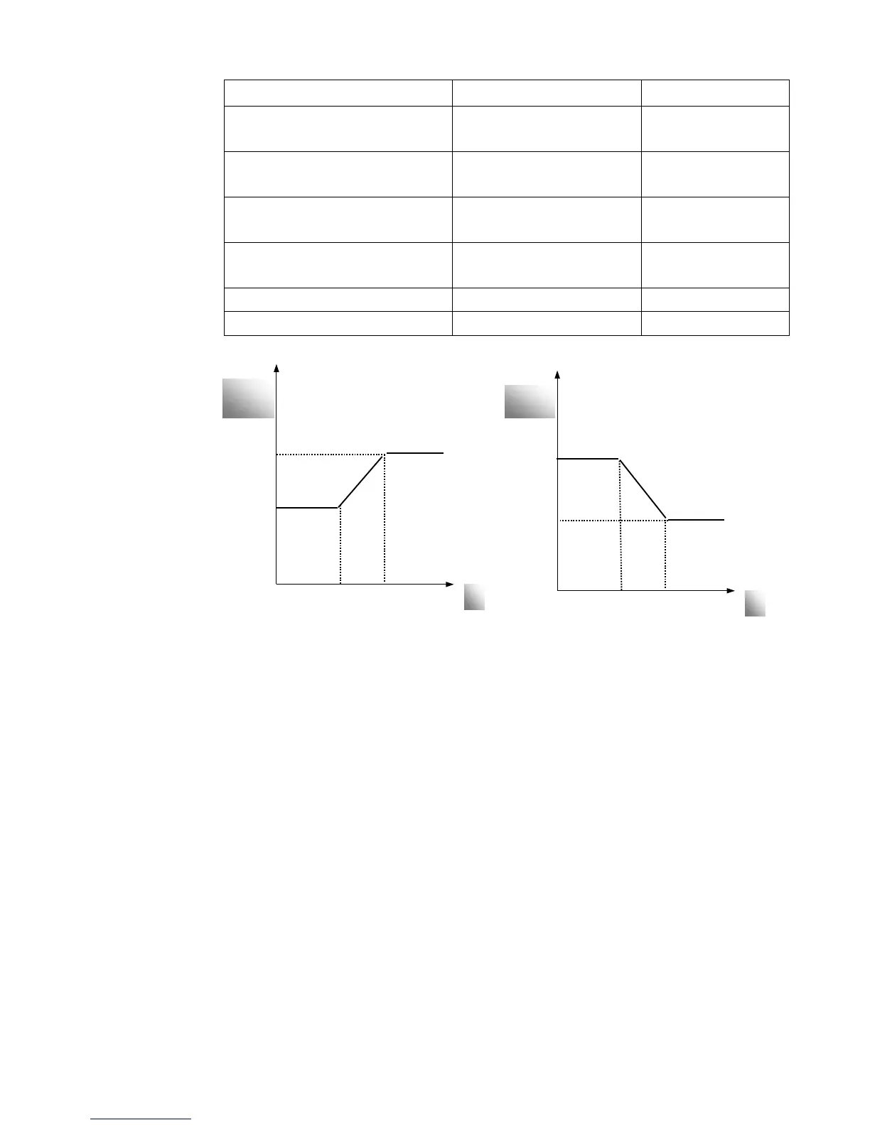
F817 PID switching frequency 1 Setting range: 0~F111 5.00
F818 PID switching frequency 2 Setting range: F817~F111 50.00
Figure 9-14 PID parameter
Dynamic response of vector control speed can be adjusted through adjusting gains of speed
loop. Increasing KP and KI can speed up dynamic response of speed loop. However, if
proportional gain or integral gain is too large, it may give rise to oscillation.
Recommended adjusting procedures:
Make fine adjustment of the value starting from the manufacturer value if the manufacturer
setting value cannot meet the needs of practical application. Be cautious that amplitude of
adjustment each time should not be too large.
In the event of weak loading capacity or slow rising of rotary speed, increase the value of KP
first under the precondition of ensuring no oscillation. If it is stable, increase the value of KI
properly to speed up response.
In the event of oscillation of current or rotary speed, decrease KP and KI properly.
In conditions of uncertainty, decrease KP at first, if there is no effect, increase KP. Then adjust
KI.
Note: Improper setting of KP and KI may result in violent oscillation of the system, or even
failure of normal operation. Set them carefully.
f

 Loading...


