Positioning and control functions
Cam controller with compensation for switching delays
105
Unit
hardware
Connector
assignment / cable
Technical dataConfigurationPositioning and
control functions
Optimization
functions
InterfacesAccessories /
options
StatusParameterError list
With the instruction V0=x (global instruction to all variables), variables V50 ... V70
will also be changed!
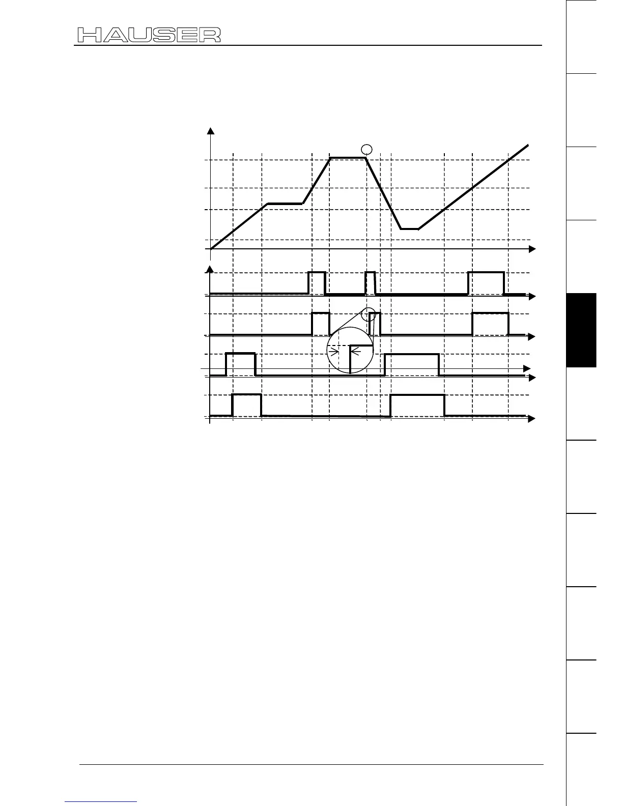
Example 1: Normal
positioning
V57
V55
V61
V59
0
1
0
1
0
1
0
1
0
1
0
1
conrtol cam 1
control cam 2
control cam 2
control cam 1
control signal 1
control signal 2
Actuator 1 (effect)
Actuator 1 (effect)
t
t
t
t
t
Position
1
error
COMPAX calculates a travel difference from the lag times of the switch elements
(
∆
p
on
and
∆
p
off
). A constant speed is assumed.
The switching signal is (with increasing setpoint)
activated by
∆
p
on
before the control cam position for On and
deactivated again by
∆
p
off
before the control cam position for Off.
Requirements for safe and time correct switching of the cam controller:
The cam positions, as well as the range
∆
p before the cam position must be moved
through at constant speed.
Problem point:
In Example 1, point ➀, the idle position is located just above V57, so that the
control cam 1 cannot be activated too early. This means that the switch-on lag of
the actuator cannot be compensated. This causes a switching error.
In this case, COMPAX activates the control cam output immediately after the
relevant positioning command is received.
Note!
Explanation
regarding cam
controller

 Loading...


