COMPAX 35XXS unit features
COMPAX 35XXM connector assignment
29
Unit
hardware
Connector
assignment / cable
Technical dataConfigurationPositioning and
control functions
Optimization
functions
InterfacesAccessories /
options
StatusParameterError list
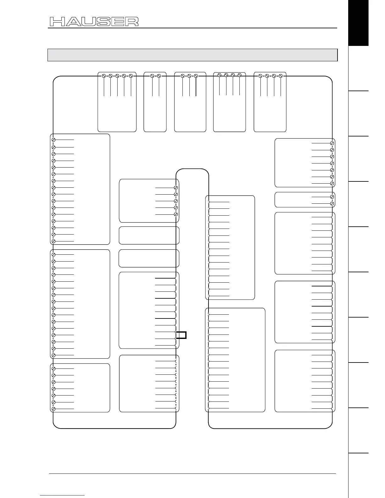
7.4.4 COMPAX 35XXM connector assignment
X13/1
Housing
X13/2
N2
X13/3
B2
X13/4
A2
X13/5
N1
X13/6
B1
X13/7
A1
X13/8
+5V
X13/9
N2/
X13/10
B2/
X13/11
A2/
X13/12
N1/
X13/13
B1/
X13/14
A1/
X13/15
GND
X10/1
I9
X10/2
I10
X10/3
I11
X10/4
I12
X10/5
I13
X10/6
I14
X10/7
I15
X10/8
I16
X10/9
O9
X10/10
O10
X10/11
O11
X10/12
O12
X10/13
O13
X10/14
O14
X10/15
O15
X10/16
O16
X9/1
+24V
X9/2
GND
X9/3
reserved
X9/4
reserved
X9/5
24V
X9/6
15-24V Emerg. stop*
X9/7
Housing
X14(15)/1
NC
X16/1
T-
X17/6
GND
X17/7
Sig.MN
X17/8
Sig. E2
X17/9
Sig. E1
X14(15)/2
RxC
X14(15)/3
TxC
X14(15)/4
RxD
X14(15)/5
TxD
X14(15)/6
RxC/
X14(15)/7
TxC/
X14(15)/8
RxD/
X14(15)/9
TxD/
X16/2
NC
X16/3
D-
X16/4
NC
X16/5
GND
X16/6
T+
X16/7
NC
X16/8
D+
X16/9
+24V
X17: DA-monitor
initiators
X14/X15:
HEDA
X16:
Absolute
encoder
X13: Encoder
X9
X10:
Input / output
I9...I16; O9...O16
X8/1
I1
X8/2
I2
X8/3
I3
X8/4
I4
X8/5
I5
X8/6
I6
X8/7
I7
X8/8
I8
X8/9
O1
X8/10
O2
X8/11
O3
X8/12
O4
X8/13
O5
X8/14
O6
X8/15
O7
X8/16
O8
X17/1
DA-channel 0
X18/-
0V
X18/+
24V
X11/4
DA-channel 2
X11/3
Override
X11/2
GND
X11/1
+24V
X11/5
DA-channel 3
X11/6
Override (old)
X11/7
Shield
X17/2
DA-channel 1
X17/3
Shield
X17/4
GND 24V
X17/5
+24V
(Option D1)
X11
X18:
Fan
X8:
Input / output
I1...I8; O1...O8
* can be parameterized
X1/2
V
PE
+LS
-LS
X21/1
+24 V
X21/2
0V
X6/2
RxD
X6/3
TxD
X6/4
DTR
X6/5
GND
X6/6
DSR
X6/7
RTS
X6/8
CTS
X6/9
+5V
X1/1
U
X1/3
W
PE
X23/3
Br'+
X23/4
Br+
X1:
Motor
HV dc and 24V
for additional
COMPAX-M
X21:
Control
voltage
X6:
RS232
X19/6
15-24V Emerg.stop
X19/7
24V
X19/8
reserved
X19/9
+24V
X19
X19/1
+24V
X19/2
GND
X19/3
Stand by P
X19/4
Stand by S
X19/5
+24V
X19/10
Enable
X19/11
Shield
X5:
output bus systems
Assignment depends on
the bus system
X7: output bus systems
Assignment depends on
the bus system
X20/2
L2
X20/1
L1
X20/3
L3
PE
X20:
AC Supply
PE
X3/1
Braking
resistance
X3/2
X22: Braking
resistance
X3/2
PE
X23/1
Br'+
X23/2
Br-
X23:
Motor brake
+24V
0V
X12/1
Housing
X12/2
+8V
X12/3
NC
X12/4
REF-
X12/5
SIN-
X12/6
NC
X12/7
GND
X12/8
ST+
X12/9
+5 V
X12/10
TEMP
X12/11
COS-
X12/12
COS+
X12/13
SIN+
X12/14
REF+
X12/15
ST-
X12: Resolver / SinCos
The assignment of X12 does not apply for the S3 option.
Enable final stage

 Loading...


