COMPAX parameter
217
Unit
hardware
Connector
assignment / cable
Technical dataConfigurationPositioning and
control functions
Optimization
functions
InterfacesAccessories /
options
StatusParameterError List:
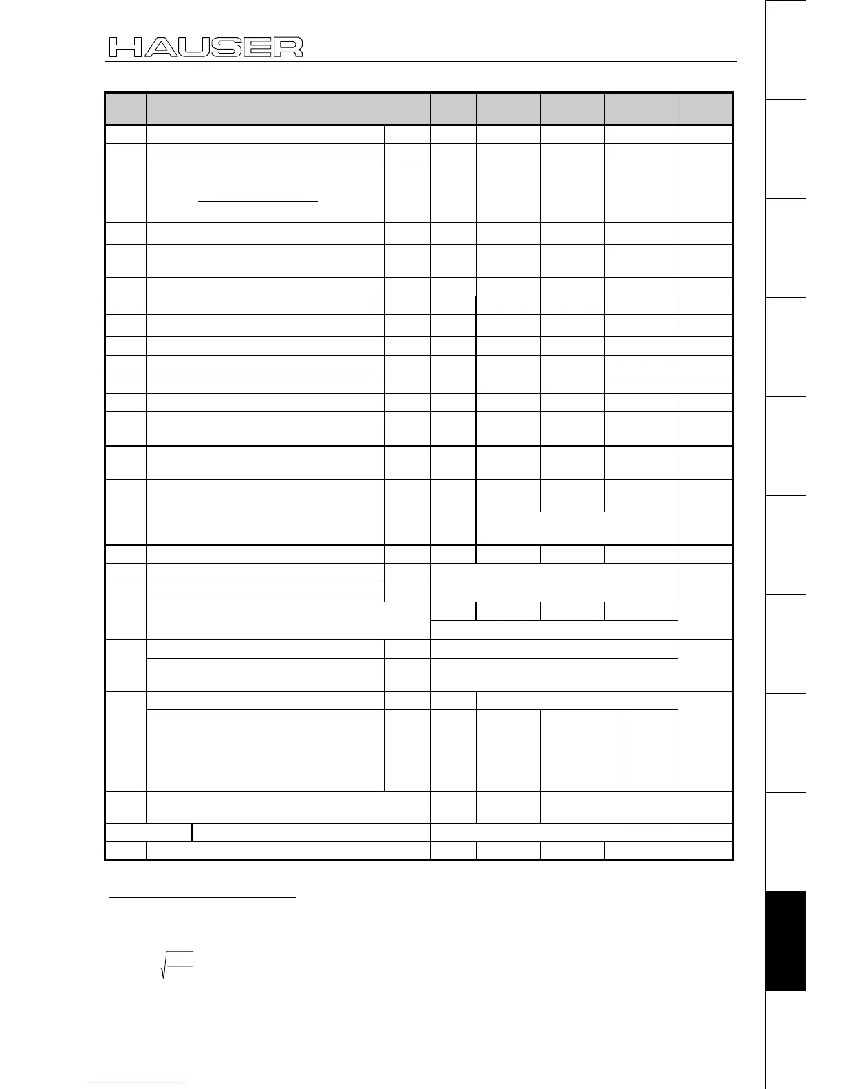
No. Meaning Unit
Minimum
value
Default
value
Maximum
value
Valid
from...
P112 Slip frequency A mHz 100 20 000
VC
Maximum speed A,SP113
Linear motor:
126
60000•1000•
=113
P
V
P
max
L
min
-1
0 9000
VC
P115 Angular speed A
% of
P104
50 100 200
VC
P116 Stator resistance A,S,L
mOh
m
0 150 000
VC
P119 Start of saturation S,L % 70 100 <P120
VC
P120 End of saturation S,L % > P119 400 400
VC
P121 Minimum stator inductivity S,L
% of
P109
10 100 100
VC
P122 Main inductivity A
µH
0 2 000 000
VC
P123 Rotor – scatter inductivity A
µH
0 200 000
VC
P124 Rotor resistance A
mOhm
0 10 000
VC
P125 Nominal voltage A V 10 400
VC
P126
Pitch length of motor magnets in µm (2
* Pole distance)
L 20 000 100 000
VC
P127
Denominator: Dash count linear
encoder per pitch length (see P133)
L- 0 1 <P133
VC
P128 Cut-off value of temperature sensor for
E48
A,S,L
Ω
0 0 20 000
VC
"0": HDX / HDY – motors
"1270": HJ – motors
P129 Resolver offset A,S,L
Degree
0 0 360
VC
P130 Resolver frequency A,S,L "2":5kHz(P4)
VC
Resolver – transformation ratio
58
A,S,L "2": ü = 0.5 (e.g. P4 resolver)
% 70 100 200
P131
Level adaptation (1/ü) for resolver or SinCos
-
sensor (from V5.61) setting aids:
59
100% ≡ 0.5; 200% ≡ 0.25; 70% ≡ 0.71;
VC
Position sensor A,S "2": 2-pol. resolver (P4)P132
With linear motors: L "10": TTL linear encoder
"11": SinCos linear encoder
VC
Sensor dash count A,S - 65 536P133
With linear motors: Dash count linear
encoder per pitch length (counter: see
P127)
Dash count per pitch length =
P133/P127
60
L
1/µm
> P127
<
8388607
VC
P134 Nominal load capacity of the external ballast
resistance (100Ω) in [W]
Watts
2
60
8000
VC
P135 – P142 Bus – parameter
P143 Encoder pulses per revolution (channel 1) 128 4096 2 000 000
VC
58
Resolver transformation ratio = ü = resolver output voltage / resolver input voltage
59
The read-in level is displayed in the square of the channel 57 optimizing display.
With P233=57 this value is in S13. Meaning:
P131=
%
S
.
100
13
4050
•
(rounded to the nearest percent)
The current default setting "2" is still possible.
Note: Resolver with Ü=1 cannot be operated!
60
Select P133 as large as possible to achieve maximum accuracy. P133 does not have fractional digits.

 Loading...


