Chapter 2 Installing PenMount 6000 Control Boards
system with screws. The control board has industry standard 3 φ screw
holes.
2. For other installation details and dipswitch settings, see
0.
3.
Connect A 6500 Control Board (for both RS-232 & USB Interface)
on
page 9.
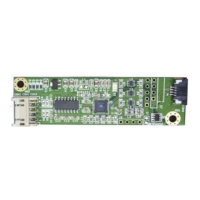
PenMount 6500 Touchscreen Control Board Upside
4. Power on the computer and the display. Install the software drivers and
utilities and calibrate the touchscreen. See
Chapter 3. Install Drivers for
6000 Boards
for details.
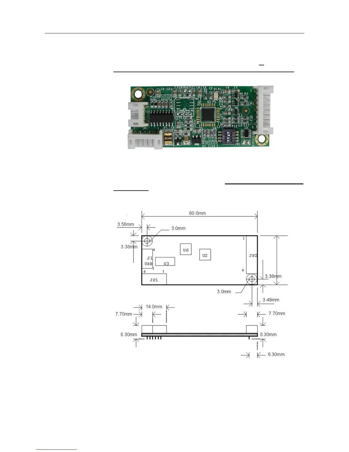
5. The mechanical diagram of PenMount 6500 Control Board:
PenMount 6500 Control Board Mechanical Diagram