2
WARNING
It is assumed that the installation, setting,
commissioning, maintenance and repair works
are carried out by qualified personnel and
checked by responsible specialists.
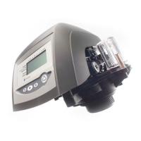
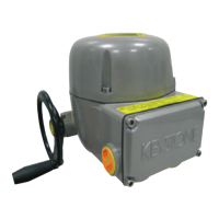
BIFFI ICON 2000
InstructIon and operatIng manual
1. GENERAL SAFETY
INSTRUCTIONS
1.1 RANGE OF APPLICATION
ICON 2000 electric actuators covered in this
I&O Manual are designed for the operation
of any kind of industrial valves used in heavy
industrial, chemical, petrochemical plants.
Biffi will not be liable for any possible damage
resulting from use in other than the designated
applications. Such risk lies entirely with the
user.
The noise emitted by the electric actuator
in normal working conditions is less than
66 dB (A) with peak value 115 dB (C). Standard
reference ISO 11202 (1st ed., 1995-12-15).
The electric actuators are designed in
accordance with the applicable international
rules and specifications but the following
regulations must be observed in any case:
- The general installation and safety
regulations.
- The plant specific regulations and
requirements.
- The proper use of personal protective devices
(glasses, clothing, gloves).
- The proper use of tools, lifting and transport
equipment.
1.2 SAFETY INSTRUCTIONS FOR
INSTALLATION IN HAZARDOUS AREA
WARNING
In case the electric actuator must be installed
in an HAZARDOUS AREA, as defined by the local
rules, it is mandatory to check if the nameplate
of the electric actuator specifies the appropriate
degree of protection. Maintenance and repair
works must be carried out by qualified personnel
and checked by responsible specialists.
ICONs are designed according to
IEC/EN 60079-0, IEC/EN 60079-1,
IEC/EN 50079-31 standards. Different types
of protection are available, depending on
the marking printed on the actuator label:
Ex d IIB Txx, Ex d IIC Txx with “Explosion proof”
terminal board enclosure, or Ex d e IIB Txx,
Ex d e IIB+H2 Txx, Ex d e IIC Txx with “Increased
safety” terminal board enclosure. They are
suitable in hazardous area classified against
the risk of explosion for the presence of gas
and dust.
IECEx INE XX.ZZZZ IECEx reference certificate
(CoC)
XX ATEX ZZZZ ATEX reference certificate
0080 Notified body for ATEX quality
assurance (INERIS)
II Group II (surface industries)
2 Category 2 apparatus
G Explosive atmospheres caused
by gas, mists or vapors
D Explosive atmospheres caused
by gas dusts
IP66/68 Degree of protection
6 Local controls........................................ 19
6.1 Description of the local operator
interface ................................................. 19
6.2 Configuration options ............................ 22
6.3 Entering the view mode ......................... 23
6.4 Entering the set-up mode ..................... 23
6.5 Exit from view and set-up modes ......... 23
7 Set-up menu .......................................... 25
8 View menu ............................................. 27
9 Set-up routines ..................................... 29
9.1 Actuator set-up ...................................... 29
9.2 Valve data ............................................... 37
9.3 Maintenance ........................................... 38
9.4 Example of set-up routine .................... 40
10 View routines ........................................ 41
10.1 Actuator set-up ...................................... 41
10.2 Name plate ............................................. 41
10.3 Valve data ............................................... 41
10.4 Maintenance ........................................... 42
10.5 Example of view routine ........................ 46
11 Maintenance .......................................... 47
11.1 Standard maintenance .......................... 47
11.2 Special maintenance ............................. 47
11.3 Lithium battery change ......................... 48
12 Troubleshooting ................................... 49
12.1 The electronics do not switch on
when powered ........................................ 49
12.2 DC output voltage not available at
the terminals .......................................... 49
12.3 The actuator does not work from
remote controls ..................................... 49
12.4 The motor is very hot and does
not start .................................................. 49
12.5 The motor runs but the actuator
does not move the valve ........................ 50
12.6 The manual override can’t be
engaged .................................................. 50
12.7 The valve does not seat correctly ......... 50
12.8 Excessive torque for valve operation .... 50
12.9 The actuator does not stop in fully
open or fully closed position ................. 50
12.10 The numeric position display
indicates “E01” ....................................... 50
12.11 Diagnostic messages ............................ 51
13 Parts list and drawings ........................ 53
13.1 Introduction ............................................ 53
Actuators have IP66/68 degree of protection
according to EN 60529.
1.2.1 Marking
 Loading...