5
BIFFI ICON 2000
InstructIon and operatIng manual
2.3 CHECKS TO BE PERFORMED BEFORE
INSTALLATION
•Makesurethevalvetobemotorizedisthe
appropriate one for coupling to the actuator.
•Theelectricalsupplycablesmustbesuitable
for the power rating (see the test certificate
that comes with the actuator).
•Gathertherighttoolsfortheassemblyand
for setting the actuator controls.
If a long storage period has occurred, before
reinstalling the actuator, please:
•CheckthestatusoftheO-ringseals.
•Checktheinstallationoftheplugsorcable
glands on the cable entries.
•Checkwhethertheenclosurecoversorthe
actuator body are cracked or broken.
•Checktheoillevelintheactuatorandtopup
if necessary.
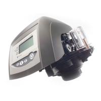
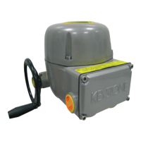
•Putthebatteriesbackintoplace
(see paragraph 11.3, Maintenance - Lithium
battery change).
3. INSTALLATION
3.1 WORKING CONDITION
The standard actuators are suitable for the
following environment temperatures:
-30°C +85°C (-22°F to +185°F)
Special versions are available for extreme
environment temperatures:
-40°C +70°C (-40°F to +158°F)
-55°C +70°C (-67°F to +158°F)
Note: only for Ex d or Ex d e versions, for
ambient temperature range, see the specific
attached addendum.
IMPORTANT
Check the "temperature environment range"
embossed on the nameplate, for the correct
utilisation with respect to the environment
temperature.
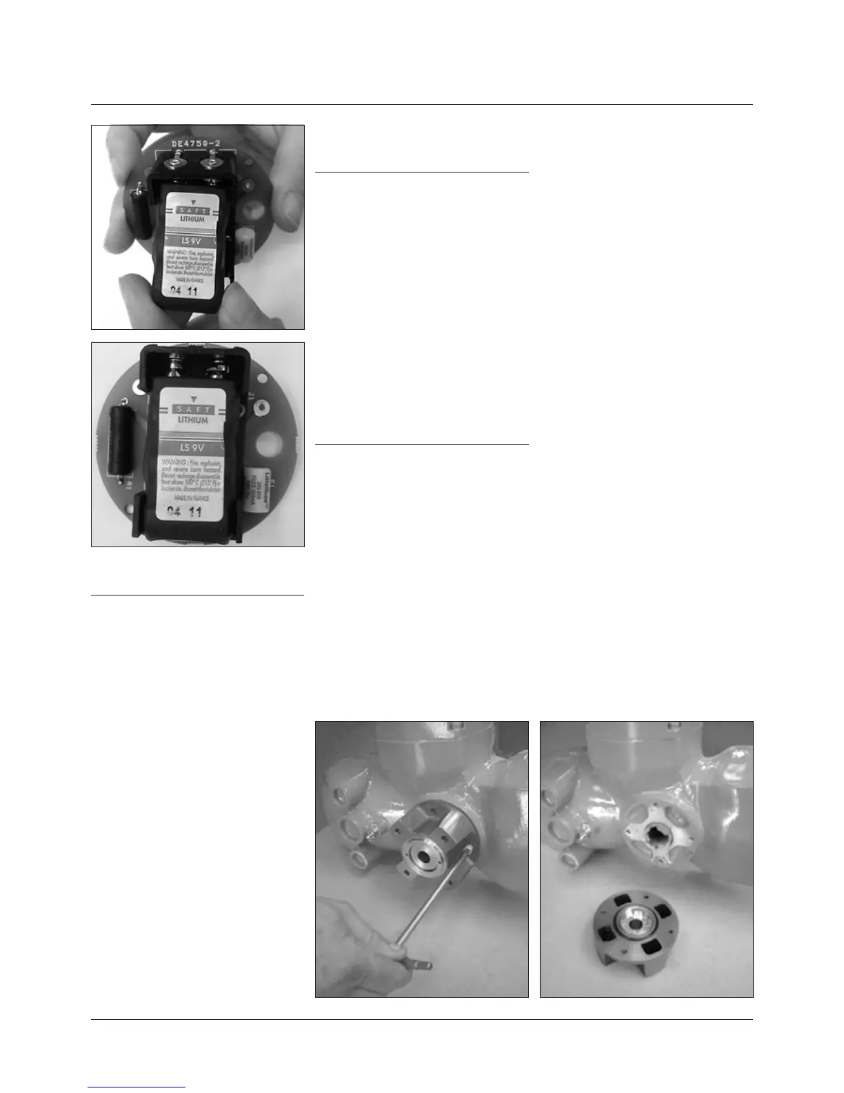
3.2 COUPLING BLOCK: DISASSEMBLY FROM
THE ACTUATOR
The bushing is delivered already assembled to
the drive sleeve, even when it is unmachined.
In order to perform the necessary machining,
remove the bushing from its housing. Remove
the fixing screws from the coupling block.
Actuator view from the coupling side, with the
block separated from the gearbox. Do not lose
the seal ring between the coupling block and
the gear reduction unit.
 Loading...